Section 7. Installation
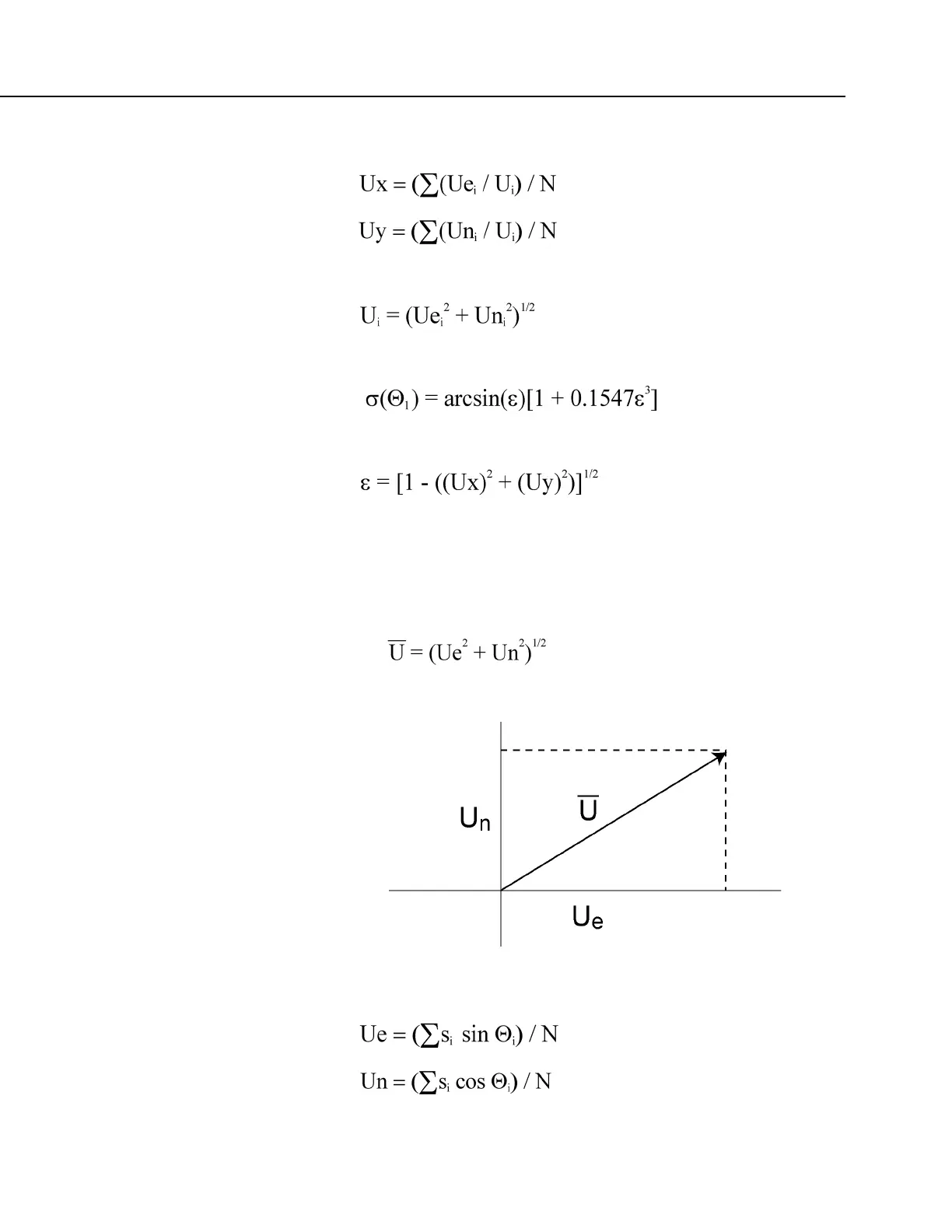
or, in the case of orthogonal sensors
where
Standard deviation of wind direction (Yamartino algorithm)
where,
and Ux and Uy are as defined above.
Mean Wind Vector
Resultant mean horizontal wind speed, Ū:
FIGURE 47: Mean Wind-Vector Graph
where for polar sensors:

 Loading...


