Section 8. Operation
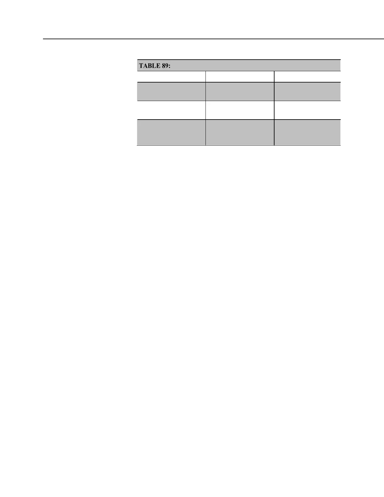
Three Specifications Differing Between P and C Terminals
P Terminal C Terminal
High-Frequency
Maximum
250 kHz 400 kHz
Input Voltage
Maximum
20 Vdc 16 Vdc
State Transition
Thresholds
Count upon transition
from
<0.9 Vdc to >2.2 Vdc
Count upon transition
from
<1.2 Vdc to >3.8 Vdc
8.1.3.8.2 Input Filters and Signal Attenuation
P and C terminals configured for pulse input have internal filters that reduce
electronic noise, which can cause false counts. However, input filters attenuate
(reduce) the amplitude (voltage) of the signal. Attenuation is a function of the
frequency of the signal. Higher-frequency signals are attenuated more. If a signal
is attenuated enough, it may not pass the detection thresholds required by the
pulse count circuitry.
The metric for filter effectiveness is τ, the filter time constant. The higher the τ
value, the less noise that gets through the filter. But, the higher the τ value, the
lower the signal frequency must be to pass the detection thresholds.
Detection thresholds, τ values, and low-level ac pulse input ranges are listed in
TABLE: Time Constants
(p. 380)
A deduction from the specifications is that while a C terminal measured with the
TimerIO() frequency measurement may be superior for clean signals, a P
terminal filter (much higher τ) may be required to get a measurement on an
electronically noisy signal.
SPEC For example, increasing voltage is required for low-level ac inputs to
overcome filter attenuation on P terminals configured for low-level ac: 8.5 ms
time constant filter (19 Hz 3 dB frequency) for low-amplitude signals; 1 ms time
constant (159 Hz 3 dB frequency) for larger (> 0.7 V) amplitude signals.
For example, the amplitude reduction that results from τ in high-frequency pulse
input mode is illustrated in figure FIGURE: Amplitude Reduction of Pulse Count
Waveform
(p. 381).

 Loading...


