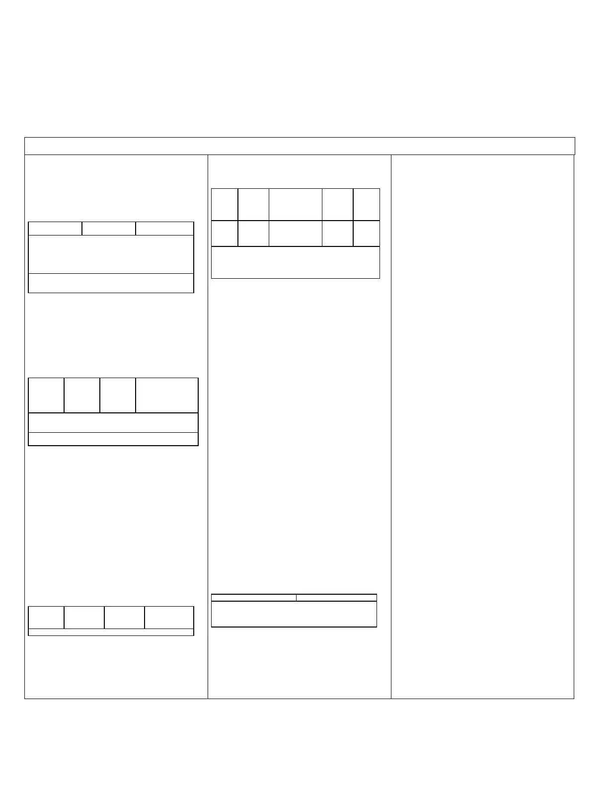
6. Specifications
-- 8 10 30
CR800 specifications are valid from ─25° to 50°C in non-condensing environments unless otherwise specified. Recalibration is recommended every three years. Critical specifications and system
configurations should be confirmed with a Campbell Scientific sales engineer before purchase.
2.0 -- 8 10 30
PROGRAM EXECUTION RATE
2.1 -- 8 10 30
10 ms to one day at 10 ms increments
3.0 -- 8 10 30
ANALOG INPUTS (SE 1–6, DIFF 1–3)
3.0.1 -- 8 10 30
Three differential (DIFF) or six single-ended (SE) individually
configured input channels. Channel expansion provided by optional
analog multiplexers.
3.1.0 -- 8 10 30
RANGES and RESOLUTION: With reference to the following
table, basic resolution (Basic Res) is the resolution of a single A/D
conversion. A DIFF measurement with input reversal has better
(finer) resolution by twice than Basic Res.
3.1.1 -- 8 10
±2500
±250
±25
±7.5
333
33.3
3.33
1.0
667
66.7
6.7
2.0
1
Range overhead of ≈9% on all ranges guarantees full-scale
voltage will not cause over-range.
2
Resolution of DIFF measurements with input reversal.
3.2 -- 8 10
ANALOG INPUT ACCURACY
3
:
±(0.06% of reading + offset
3
), 0° to 40°C
±(0.12% of reading + offset
3
), -25° to 50°C
±(0.18% of reading + offset
3
), -55° to 85°C (-XT only)
3.2.1 -- 8 10 30
3
Accuracy does not include sensor and measurement noise.
Offset definitions:
Offset = 1.5 x Basic Res + 1.0 µV (for DIFF measurement w/ input
reversal)
Offset = 3 x Basic Res + 2.0 µV (for DIFF measurement w/o input
reversal)
Offset = 3 x Basic Res + 3.0 µV (for SE measurement)
3.3 -- 8 10 30
ANALOG MEASUREMENT SPEED:
3.3.1 -- 8 10
4
gration
Type
Inte-
gration
Settling
with
no
with
Input
_60Hz
5
16.67 ms
3 ms
≈20 ms
≈40 ms
4
Includes 250 μs for conversion to engineering units.
5
AC line noise filter
3.4 -- 8 10 30
3.4.1 -- 8 10 30
INPUT-NOISE VOLTAGE: For DIFF measurements with input
reversal on ±2.5 mV input range (digital resolution dominates for
higher ranges):
250 μs Integration: 0.34 μV RMS
50/60 Hz Integration: 0.19 μV RMS
3.4.2 -- 8 10 30
INPUT LIMITS: ±5 Vdc
3.4.3 -- 8 10 30
DC COMMON-MODE REJECTION: >100 dB
3.4.4 -- 8 10 30
NORMAL-MODE REJECTION: 70 dB @ 60 Hz when using 60
Hz rejection
3.4.5 -- 8 10 30
INPUT VOLTAGE RANGE W/O MEASUREMENT
CORRUPTION: ±8.6 Vdc max.
3.4.6 -- 8 10 30
SUSTAINED-INPUT VOLTAGE W/O DAMAGE: ±16 Vdc max
3.4.7 -- 8 10 30
INPUT CURRENT: ±1 nA typical, ±6 nA max. @ 50°C; ±90 nA
@ 85°C
3.4.8 -- 8 10 30
INPUT RESISTANCE: 20 GΩ typical
3.4.9 -- 8 10 30
ACCURACY OF BUILT-IN REFERENCE JUNCTION
THERMISTOR (for thermocouple measurements):
±0.3°C, -25° to 50°C
±0.8°C, -55° to 85°C (-XT only)
4.0 -- 8 10 30
ANALOG OUTPUTS (VX 1–2)
4.0.1 -- 8
Two switched voltage outputs sequentially active only during
measurement.
4.0.2 -- 8 10 30
RANGES AND RESOLUTION:
4.1 -- 8 10
Channel
Range
Resolu-
tion
Source
/ Sink
4.2 -- 8 10
ANALOG OUTPUT ACCURACY (VX):
±(0.06% of setting + 0.8 mV, 0° to 40°C
±(0.12% of setting + 0.8 mV, -25° to 50°C
±(0.18% of setting + 0.8 mV, -55° to 85°C (-XT only)
4.4 -- 8 10 30
VX FREQUENCY SWEEP FUNCTION: Switched outputs
provide a programmable swept frequency, 0 to 2500 mV square
waves for exciting vibrating wire transducers.
3.5.0 -- 8 10 30
PERIOD AVERAGE
3.5.0a -- 8 10 30
Any of the 6 SE analog inputs can be used for period averaging.
Accuracy is ±(0.01% of reading + resolution), where resolution is
136 ns divided by the specified number of cycles to be measured.
INPUT AMPLITUDE AND FREQUENCY:
3.5.1 -- 8 10
Signal
Min
10
33
mV25
mV7_5
10
5
2
2
10
62
50
8
6
Signal to be centered around Threshold (see PeriodAvg()
instruction).
7
Signal to be centered around ground.
8
The maximum frequency = 1/(twice minimum pulse width)
for 50% of duty cycle signals.
5.0 -- 8 10 30
RATIOMETRIC MEASUREMENTS
5.1 -- 8 10
MEASUREMENT TYPES: The CR800 provides ratiometric
resistance measurements using voltage excitation. Three switched
voltage excitation outputs are available for measurement of four-
and six-wire full bridges, and two-, three-, and four-wire half
bridges. Optional excitation polarity reversal minimizes dc errors.
5.2 -- 8 10
RATIOMETRIC MEASUREMENT ACCURACY
9,11
Note Important assumptions outlined in footnote 9:
±(0.04% of Voltage Measurement + Offset
12
)
5.2.1 -- 8 10 30
9
Accuracy specification assumes excitation reversal for excitation
voltages < 1000 mV. Assumption does not include bridge resistor
errors and sensor and measurement noise.
11
Estimated accuracy, ∆X (where X is value returned from
measurement with Multiplier =1, Offset = 0):
BRHalf() Instruction: ∆X = ∆V
1/
V
X
.
BRFull() Instruction
:
∆X = 1000 x ∆V
1/
V
X
, expressed as mV•V
-
1
.
Note ∆V
1
is calculated from the ratiometric measurement
accuracy. See manual section Resistance Measurements
for more
information.
12
Offset definitions:
Offset = 1.5 x Basic Res + 1.0 µV (for DIFF measurement w/ input
reversal)
Offset = 3 x Basic Res + 2.0 µV (for DIFF measurement w/o input
reversal)
Offset = 3 x Basic Res + 3.0 µV (for SE measurement)
Note Excitation reversal reduces offsets by a factor of two.
6.0 -- 8 10 30
PULSE COUNTERS (P 1–2)
6.0.1 -- 8 10 30
Two inputs individually selectable for switch closure, high-
frequency pulse, or low-level ac. Independent 24-bit counters for
each input.
6.1 -- 8 10 30
MAXIMUM COUNTS PER SCAN: 16.7 x 10
6
6.2 -- 8 10 30
SWITCH CLOSURE MODE:
Minimum Switch Closed Time: 5 ms
Minimum Switch Open Time: 6 ms
Max. Bounce Time: 1 ms open without being counted
6.3 -- 8 10 30
HIGH-FREQUENCY PULSE MODE:
Maximum-Input Frequency: 250 kHz
Maximum-Input Voltage: ±20 V
Voltage Thresholds: Count upon transition from below 0.9 V to
above 2.2 V after input filter with 1.2 μs time constant.
6.4 -- 8 10 30
LOW-LEVEL AC MODE: Internal ac coupling removes dc offsets
up to ±0.5 Vdc.
Input Hysteresis: 12 mV RMS @ 1 Hz
Maximum ac-Input Voltage: ±20 V
Minimum ac-Input Voltage:
6.4.1 -- 8 10 30
200
2000
0.5 to 200
0.3 to 10,000
7.0 -- 8 10 30
DIGITAL I/O PORTS (C 1–4)
7.0.1 -- 8 10 30
Four ports software selectable as binary inputs or control outputs.
Provide on/off, pulse width modulation, edge timing, subroutine
interrupts / wake up, switch closure pulse counting, high-frequency
pulse counting, asynchronous communications (UARTs), and SDI-
12 communications. SDM communications are also supported.
7.1 -- 8 10 30
LOW FREQUENCY MODE MAX: <1 kHz
7.2 -- 8 10 30
HIGH FREQUENCY MODE MAX: 400 kHz
7.3 -- 8 10 30
SWITCH-CLOSURE FREQUENCY MAX: 150 Hz
7.4 -- 8 10 30
EDGE-TIMING RESOLUTION: 540 ns
7.5 -- 8 10 30
OUTPUT VOLTAGES (no load): high 5.0 V ±0.1 V; low < 0.1 V
7.6 -- 8 10 30
OUTPUT RESISTANCE: 330 Ω
7.7 -- 8 10 30
INPUT STATE: high 3.8 to 16 V; low -8.0 to 1.2 V
7.8 -- 8 10 30
INPUT HYSTERISIS: 1.4 V
7.9 -- 8 10 30
INPUT RESISTANCE:
100 kΩ with inputs < 6.2 Vdc
220 Ω with inputs ≥ 6.2 Vdc
7.10 -- 8 10 30
SERIAL DEVICE / RS-232 SUPPORT: 0 to 5 Vdc UART
7.12 -- 8 10 30
SWITCHED 12 Vdc (SW12)
One independent 12 Vdc unregulated terminal switched on and off
under program control. Thermal fuse hold current = 900 mA at
20°C, 650 mA at 50°C, and 360 mA at 85°C.
8.0 -- 8 10 30
COMPLIANCE
8.1 -- 8 10 30
View the EU Declaration of Conformity at
www.campbellsci.com/cr800
9.0 -- 8 10 30
COMMUNICATION
9.1 -- 8 10 30
RS-232 PORTS:
DCE nine-pin: (not electrically isolated) for computer connection
or connection of modems not manufactured by Campbell
Scientific.
COM1 to COM2: two independent Tx/Rx pairs on control ports
(non-isolated); 0 to 5 Vdc UART
Baud Rate: selectable from 300 bps to 115.2 kbps.
Default Format: eight data bits; one stop bits; no parity.
Optional Formats: seven data bits; two stop bits; odd, even parity.
9.2 -- 8 10 30
CS I/O PORT: Interface with comms peripherals manufactured by
Campbell Scientific.
9.3 -- 8 10 30
SDI-12: Digital control ports C1, C3 are individually configurable
and meet SDI-12 Standard v. 1.3 for datalogger mode. Up to ten
SDI-12 sensors are supported per port.
9.5 -- 8 10 30
PROTOCOLS SUPPORTED: PakBus, AES-128 Encrypted
PakBus, Modbus, DNP3, FTP, HTTP, XML, HTML, POP3,
SMTP, Telnet, NTCIP, NTP, web API, SDI-12, SDM.
10.0 -- 8 10 30
SYSTEM
10.1 -- 8 10 30
PROCESSOR: Renesas H8S 2322 (16-bit CPU with 32-bit internal
core running at 7.3 MHz)
10.2 -- 8 10 30
MEMORY: 2 MB of flash for operating system; 4 MB of battery-
backed SRAM for CPU, CRBasic programs, and data.
10.3 -- 8 10 30
REAL-TIME CLOCK ACCURACY: ±3 min. per year. Correction
via GPS optional.
10.4 -- 8 10 30
RTC CLOCK RESOLUTION: 10 ms
11.0 -- 8 10 30
SYSTEM POWER REQUIREMENTS
11.1 -- 8 10 30
VOLTAGE: 9.6 to 16 Vdc
11.2 -- 8 10
INTERNAL BATTERY: 1200 mAhr lithium battery for clock and
SRAM backup. Typically provides three years of back-up.
11.3 -- 8 10 30
EXTERNAL BATTERIES: Optional 12 Vdc nominal alkaline and
rechargeable available. Power connection is reverse polarity
protected.
11.4 -- 8 10 30
TYPICAL CURRENT DRAIN at 12 Vdc:
Sleep Mode: 0.7 mA typical; 0.9 mA maximum
1 Hz Sample Rate (one fast SE meas.): 1 mA
100 Hz Sample Rate (one fast SE meas.): 16 mA
100 Hz Sample Rate (one fast SE meas. with RS-232
communications): 28 mA
Active external keyboard display adds 7 mA (100 mA with
backlight on).
12.0 -- 8 10 30
PHYSICAL
12.1
DIMENSIONS: 241 x 104 x 51 mm (9.5 x 4.1 x 2 in.) ; additional
clearance required for cables and leads.
12.2
MASS / WEIGHT: 0.7 kg / 1.5 lbs
13.0
WARRANTY
13.1
Warranty is stated in the published price list and in opening pages
of this and other user manuals.

 Loading...


