Section 4. Quickstart
4.6.4.2 Procedure: (Short Cut Steps 6 to 7)
6. Double-click Type T (copper-constantan) Thermocouple to add it into the
Selected column. A dialog window is presented with several fields. By
immediately clicking OK, you accept default options that include selection of
1 sensor and PTemp_C as the reference temperature measurement.
Note BattV (battery voltage) and PTempC (wiring panel temperature)
are default measurements. During normal operations, battery and
temperature can be recorded at least daily to assist in monitoring system
status.
7. In the left pane of the main Short Cut window, click Wiring Diagram. Attach
the physical type-T thermocouple to the CR800 as shown in the diagram.
Click on 3. Sensors in the left pane to return to the sensor selection screen.
4.6.4.3 Procedure: (Short Cut Step 8)
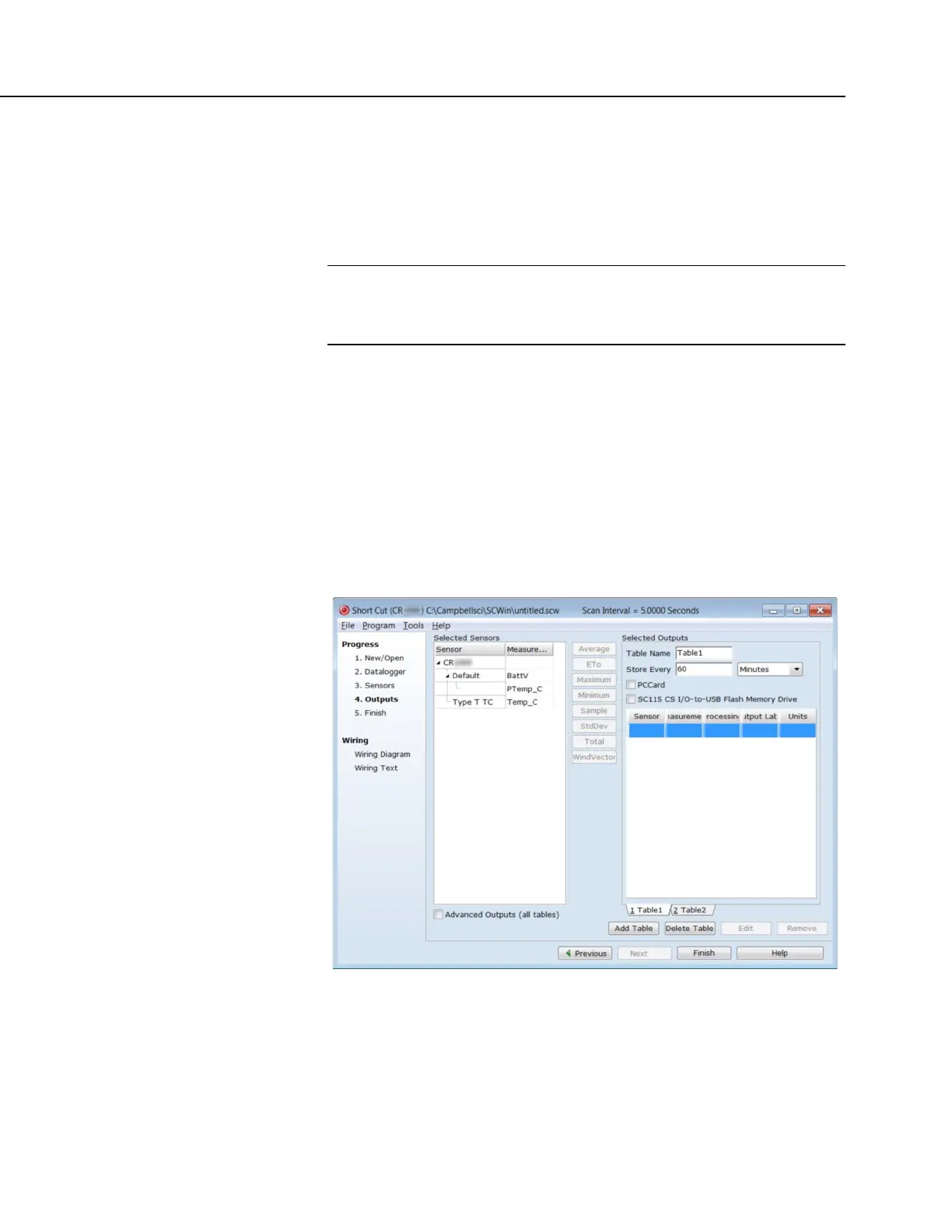
8. As shown in the following figure, click Next to advance to the Outputs tab,
which displays the list Selected Sensors to the left and data storage tables to
the right under Selected Outputs.
FIGURE 5: Short Cut Outputs Tab
4.6.4.4 Procedure: (Short Cut Steps 9 to 12)
9. As shown in the right-most pane of the previous figure, two output tables (1
Table1 and 2 Table2 tabs) are initially configured. Both tables have a Store
Every field and a drop-down list from which to select the time units. These
are used to set the time intervals when data are stored.

 Loading...


