Section 8. Operation
Note Peripheral devices are available from Campbell Scientific to expand
the number of pulse input channels measured by the CR800. See
Measurement and Control Peripherals — List
(p. 562).
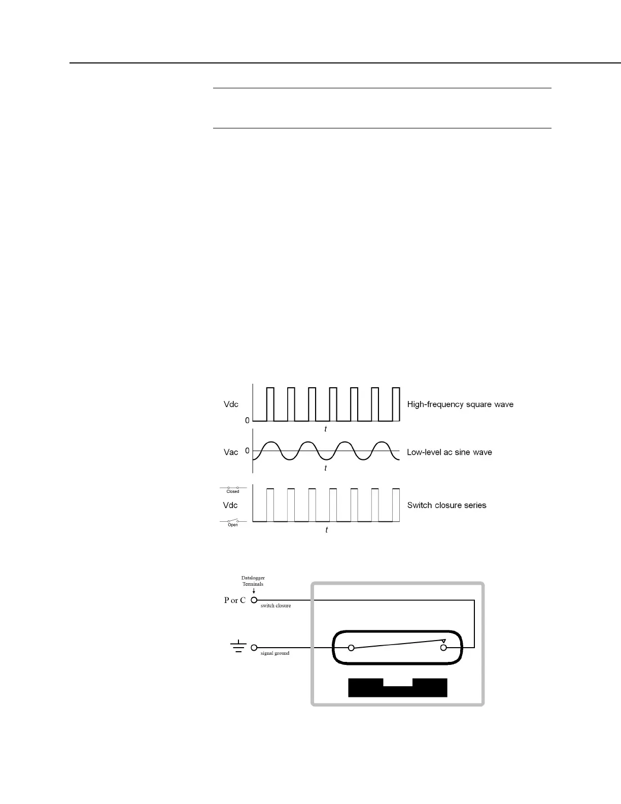
The figure Pulse Sensor Output Signal Types (p. 71) illustrates pulse signal types
measurable by the CR800:
• low-level ac
• high-frequency
• switch closure
The figure Switch Closure Pulse Sensor
(p. 370) illustrates the basic internal circuit
and the external connections of a switch closure pulse sensor. The table Pulse
Measurements: Terminals and Programming
(p. 371) summarizes available
measurements, terminals available for those measurements, and the CRBasic
instructions used. The number of terminals configurable for pulse input is
determined from the table CR800 Terminal Definitions
(p. 58).
FIGURE 85: Pulse Sensor Output Signal Types
FIGURE 86: Switch Closure Pulse Sensor

 Loading...


