Appendix B. Serial Port Pinouts
B.2 RS-232 Communication Port
B.2.1 Pin Outs
Pin configuration for the CR800 RS-232 nine-pin port is listed in table Pinout of
CR800 RS-232 D-Type Connector Port
(p. 554). Information for using a null
modem with RS-232 is given in table Standard Null-Modem Cable Pinout
(p. 554).
The CR800 RS-232 port functions as either a DCE (data communication
equipment) or DTE (data terminal equipment) device. For RS-232 port to
function as a DTE device, a null modem cable is required. The most common use
of RS-232 port is as a connection to a computer DTE device. A standard DB9-to-
DB9 cable can connect the computer DTE device to the CR800 DCE device. The
following table describes RS-232 pin function with standard DCE-naming
notation.
Note Pins 1, 4, 6, and 9 function differently than a standard DCE device.
This is to accommodate a connection to a modem or other DCE device via
a null modem.
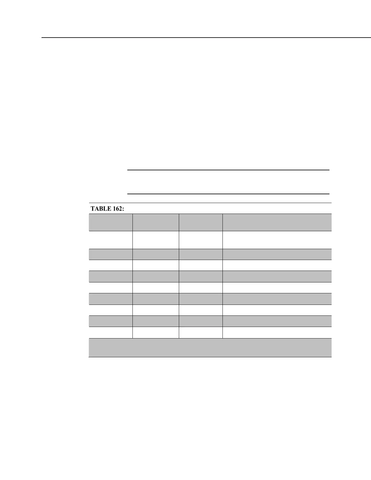
Pin Out of CR800 RS-232 D-Type Connector Port
Pin
Number
Function
Input (I)
Output (O)
Description
1
1
DTR
(tied to pin 6)
O Data terminal ready
2 TXD O Asynchronous data transmit
3 RXD I Asynchronous data receive
4
1
N/A N/A Not connected
5 GND GND Ground
6
1
DTR O Data terminal ready
7 CTS I Clear to send
8 RTS O Request to send
9
1
RI I Ring
1
Different pin function compared to a standard DCE device. This pin out accommodates a
connection to modem or other DCE devices over a null-modem cable.

 Loading...


