Section 7. Installation
Scan(100,mSec,100,0)
'Measure Bridge Resistance
BrFull(Raw_mVperV,1,mV25,1,Vx1,1,2500,True ,True ,0,250,1.0,0)
'Calculate Strain for 1/4 Bridge (1 Active Element)
StrainCalc(microStrain,1,Raw_mVperV,Zero_mVperV,1,GF_Adj,0)
'Steps (1) & (3): Zero Calibration
'Balance bridge and set Zero_Mode = 1 in numeric monitor. Repeat after
'shunt calibration.
FieldCalStrain(10,Raw_mVperV,1,0,Zero_mVperV,Zero_Mode,0,1,10,0 ,microStrain)
'Step (2) Shunt Calibration
'After zero calibration, and with bridge balanced (zeroed), set
'KnownRes = to gage resistance (resistance of gage at rest), then set
'Shunt_Mode = 1. When Shunt_Mode increments to 3, position shunt resistor
'and set KnownRes = shunt resistance, then set Shunt_Mode = 4.
FieldCalStrain(13,MicroStrain,1,GF_Adj,0,Shunt_Mode,KnownRes,1,10,GF_Raw,0)
CallTable CalHist
NextScan
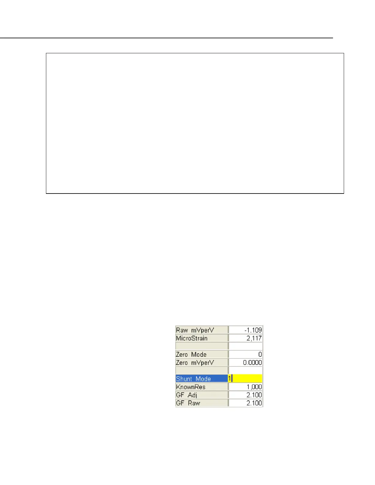
7.7.11.6.3 FieldCalStrain() Quarter-Bridge Shunt Example
With CRBasic example FieldCalStrain() Calibration (p. 230) sent to the CR800, and
the strain gage stable, use the CR1000KD Keyboard/Display or software numeric
monitor to change the value in variable KnownRes to the nominal resistance of
the gage, 1000 Ω, as shown in figure Strain Gage Shunt Calibration Start
(p. 231).
Set Shunt_Mode to 1 to start the two-point shunt calibration. When Shunt_Mode
increments to 3, the first step is complete.
To complete the calibration, shunt R1 with the 249 kΩ resistor. Set variable
KnownRes to 249000. As shown in figure Strain Gage Shunt Calibration Finish
(p. 232),
set Shunt_Mode to 4. When Shunt_Mode = 6, shunt calibration is
complete.
FIGURE 60: Strain Gage Shunt
Calibration Start

 Loading...


