Section 5. Overview
communications and SDI-12 communications. Table CR800 Terminal
Definitions
(p. 58) summarizes available options.
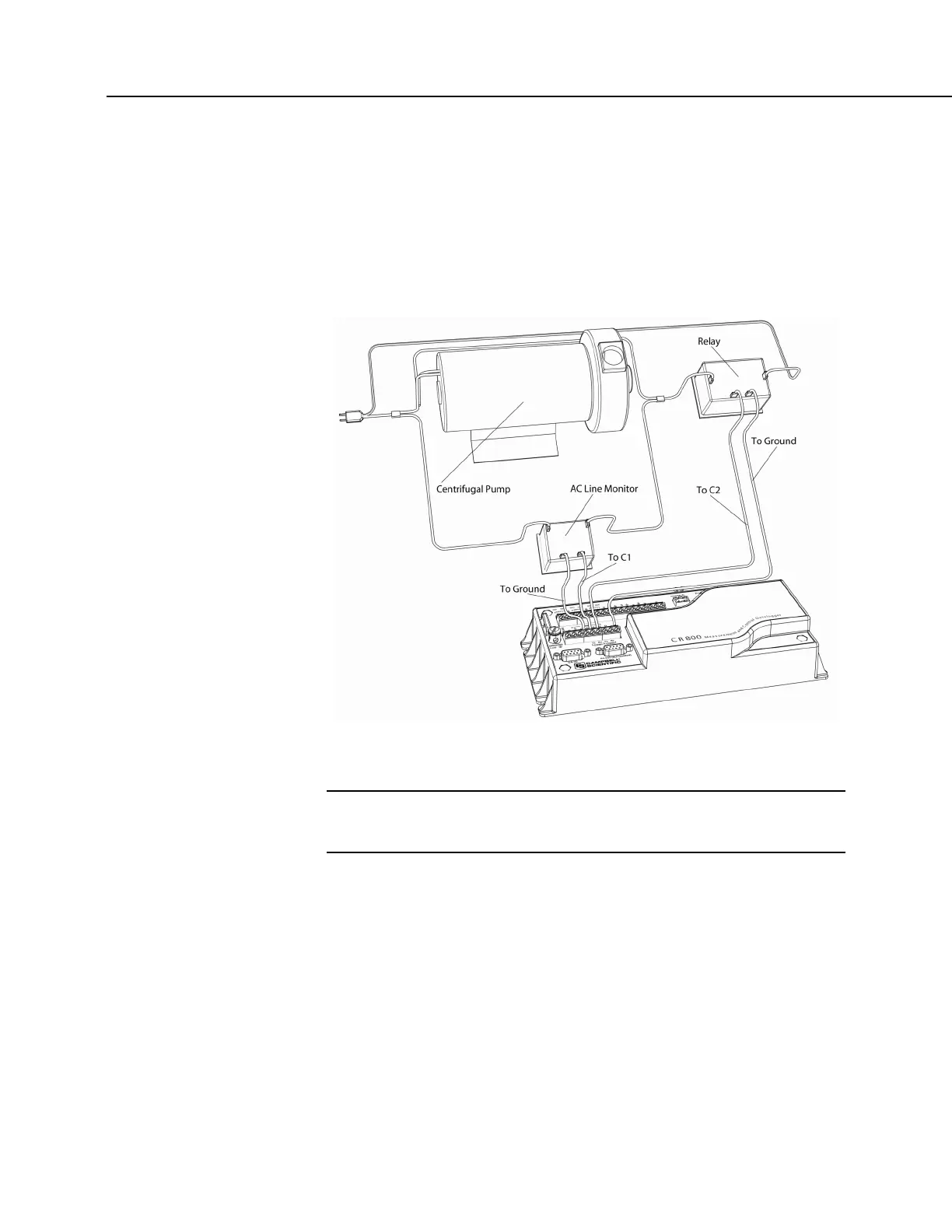
Figure Control and Monitoring with C Terminals
(p. 60) illustrates a simple
application wherein a C terminal configured for digital input and another
configured for control output are used to control a device (turn it on or off) and
monitor the state of the device (whether the device is on or off).
FIGURE 17: Control and Monitoring with C Terminals
5.1.1.2 Voltage Excitation — Overview
Related Topics:
• Voltage Excita (p. 60)tion — Specifications
• Voltage Excitation — Overview
(p. 60)
The CR800 has several terminals designed to supply switched voltage to
peripherals, sensors, or control devices:
• Voltage Excitation (switched-analog output) — Vx terminals supply
precise voltage. These terminals are regularly used with resistive-bridge
measurements..
• Digital I/O — C terminals configured for on / off and PWM (pulse width
modulation) or PDM (pulse duration modulation) on C4.
• Switched 12 Vdc — SW12 terminals. Primary battery voltage under
program control to control external devices (such as humidity sensors)

 Loading...


