Section 7. Installation
'SIMULATE SIGNAL THEN MAKE THE MEASUREMENT
'Zero calibration is applied when variable CalMode = 6
ExciteV(Vx1,SimulatedSalinitySignal,0)
VoltSE(Salinity,1,mV2500,1,1,0,250,0.05,SalinityOffset)
'PERFORM AN OFFSET CALIBRATION.
'Start by setting variable CalMode = 1. Finished when variable CalMode = 6.
'FieldCal(Function, MeasureVar, Reps, MultVar, OffsetVar, Mode, KnownVar, Index, Avg)
FieldCal(1,Salinity,1,0,SalinityOffset,CalMode,KnownSalinity,1,30)
'If there was a calibration, store calibration values into data table CalHist
CallTable(CalHist)
NextScan
7.7.11.5.3 FieldCal() Slope and Offset (Opt 2) Example
Most CRBasic measurement instructions have a multiplier and offset parameter.
FieldCal() Option 2 adjusts the multiplier and offset arguments such that the
output of the sensor being calibrated is set to a value consistent with the linear
relationship that intersects two known points sequentially entered in the
FieldCal() KnownVar parameter. Subsequent measurements are scaled with the
same multiplier and offset.
Example Case: A meter measures the volume of water flowing through a pipe.
Multiplier and offset are known to drift, so a two-point calibration is required
periodically at known flow rates. The following procedure adjusts multiplier and
offset to correct for meter drift as shown in the calibration report below. Note that
the flow meter outputs millivolts inversely proportional to flow.
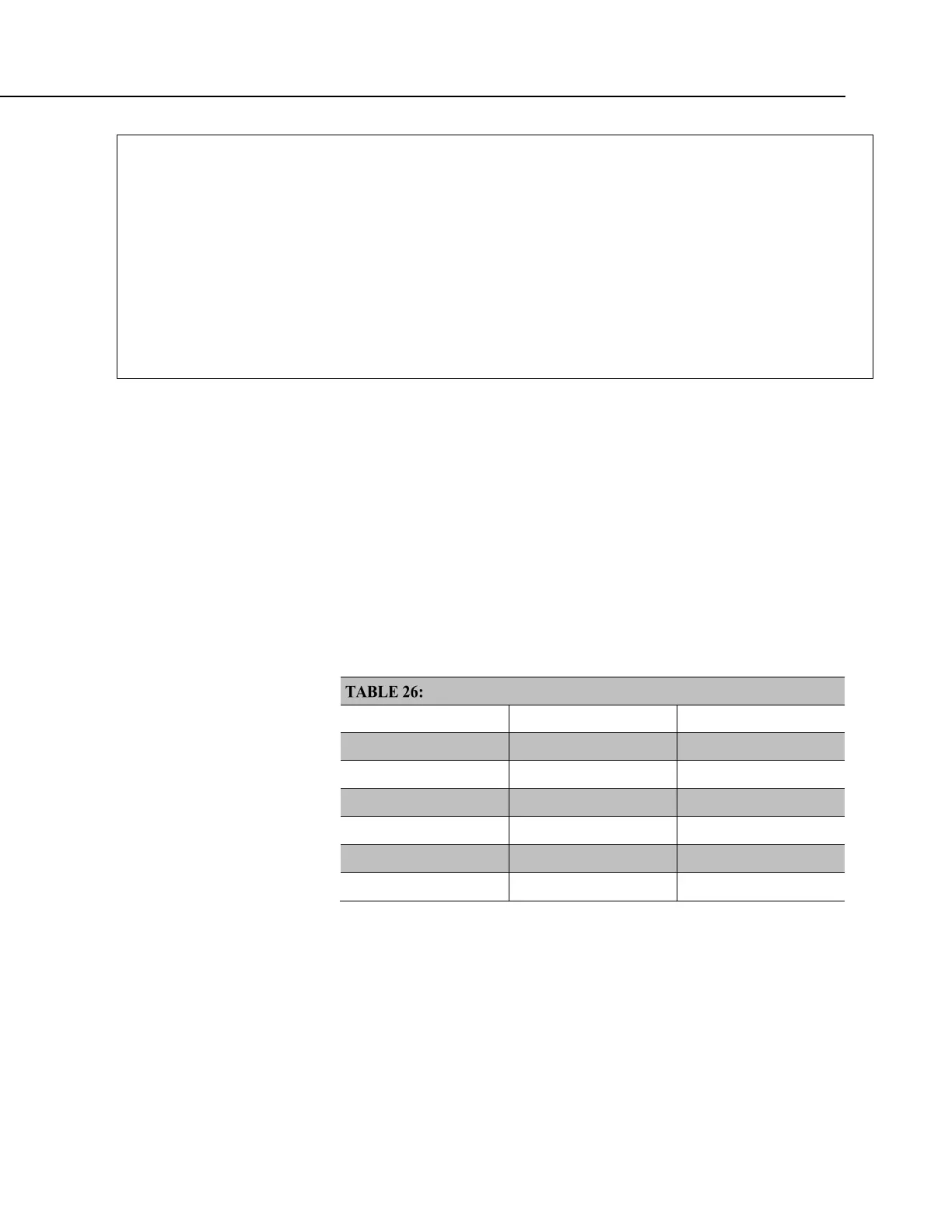
Calibration Report for Flow Meter
CRBasic Variable At Deployment At Seven-Day Service
SimulatedFlowSignal
300 mV 285 mV
KnownFlow
30 L/s 30 L/s
SimulatedFlowSignal
550 mV 522 mV
KnownFlow
10 L/s 10 L/s
FlowMultiplier
-0.0799 L/s/mV -0.0841 L/s/mV
FlowOffset
53.90 L 53.92 L
1. Send CRBasic example FieldCal() Two-Point Slope and Offset (p. 224) to the
CR800.
2. To place the simulated flow sensor in a simulated calibration condition (in the
field a real sensor would be placed in a condition of know flow), place a
jumper wire between terminals VX1 and SE1.
3. Perform the simulated deployment calibration as follows:

 Loading...


