Section 8. Operation
8.1.8 Cabling Effects — Details
Related Topics:
• Cabling Effects — Overview (p. 76)
• Cabling Effects — Details
(p. 386)
Sensor cabling can have significant effects on sensor response and accuracy. This
is usually only a concern with sensors acquired from manufacturers other than
Campbell Scientific. Campbell Scientific sensors are engineered for optimal
performance with factory-installed cables.
8.1.8.1 Analog Sensor Cabling
Cable length in analog sensors is most likely to affect the signal settling time. For
more information, see Signal Settling Time
(p. 318).
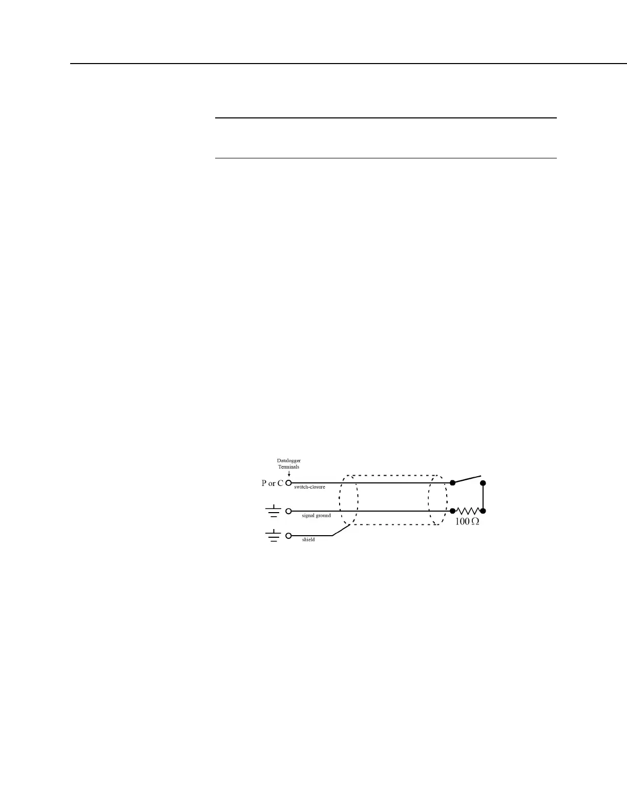
8.1.8.2 Pulse Sensor Cabling
Because of the long interval between switch closures in tipping-bucket rain gages,
appreciable capacitance can build up between wires in long cables. A built-up
charge can cause arcing when the switch closes and so shorten switch life. As
shown in figure Current-Limiting Resistor in a Rain Gage Circuit
(p. 386), a 100 Ω
resistor is connected in series at the switch to prevent arcing. This resistor is
installed on all rain gages currently sold by Campbell Scientific.
FIGURE 92: Current-Limiting Resistor in a Rain Gage
Circuit
8.1.8.3 RS-232 Sensor Cabling
RS-232 sensor cable lengths should be limited to 50 feet.
8.1.8.4 SDI-12 Sensor Cabling
The SDI-12 standard allows cable lengths of up to 200 feet. Campbell Scientific
does not recommend SDI-12 sensor lead lengths greater than 200 feet; however,
longer lead lengths can sometimes be accommodated by increasing the wire gage
or powering the sensor with a second 12 Vdc power supply placed near the
sensor.

 Loading...


