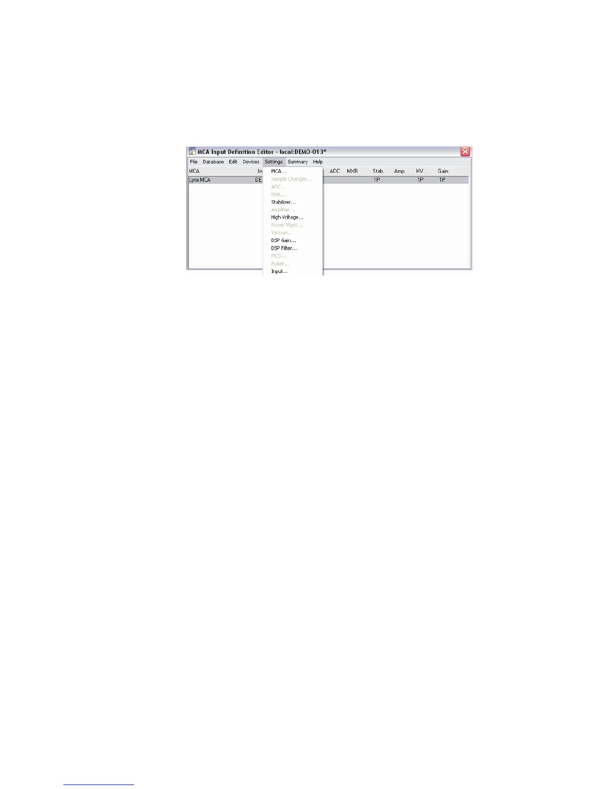
10. Parameter Settings
By selecting the Stabilizer, High Voltage and DSP Gain and Filter selections, edits and
setup scan be made within the unit itself via the setup screens.
Interpreting the Definition Entry
Adding MCAs puts more than just the name of the MCA in the definition table.
Note The letter following the unit number in some of the Definition Table items
identifies how the unit is controlled:
– M for a manually-controlled unit
– P for a programmable unit
MCA
This is the type of MCA device being used for this particular entry in the table.
Input
This is the name that will be used to refer to this specific hardware entry in the table.
The MID Editor automatically assigns these names sequentially as DET nn, starting
with nn=01. You can easily edit this assignment to an input name of your choice.
Size
This shows the number of data channels assigned to this input.
Gain
This column describes the DSP Gain device associated with the Lynx DSP.
Chapter 3 - System Setup
32 Lynx™ Digital Signal Analyzer
Figure 25 - Lynx Configuration Settings options