133
6
Chapter 6 Starting and Stopping Measurement
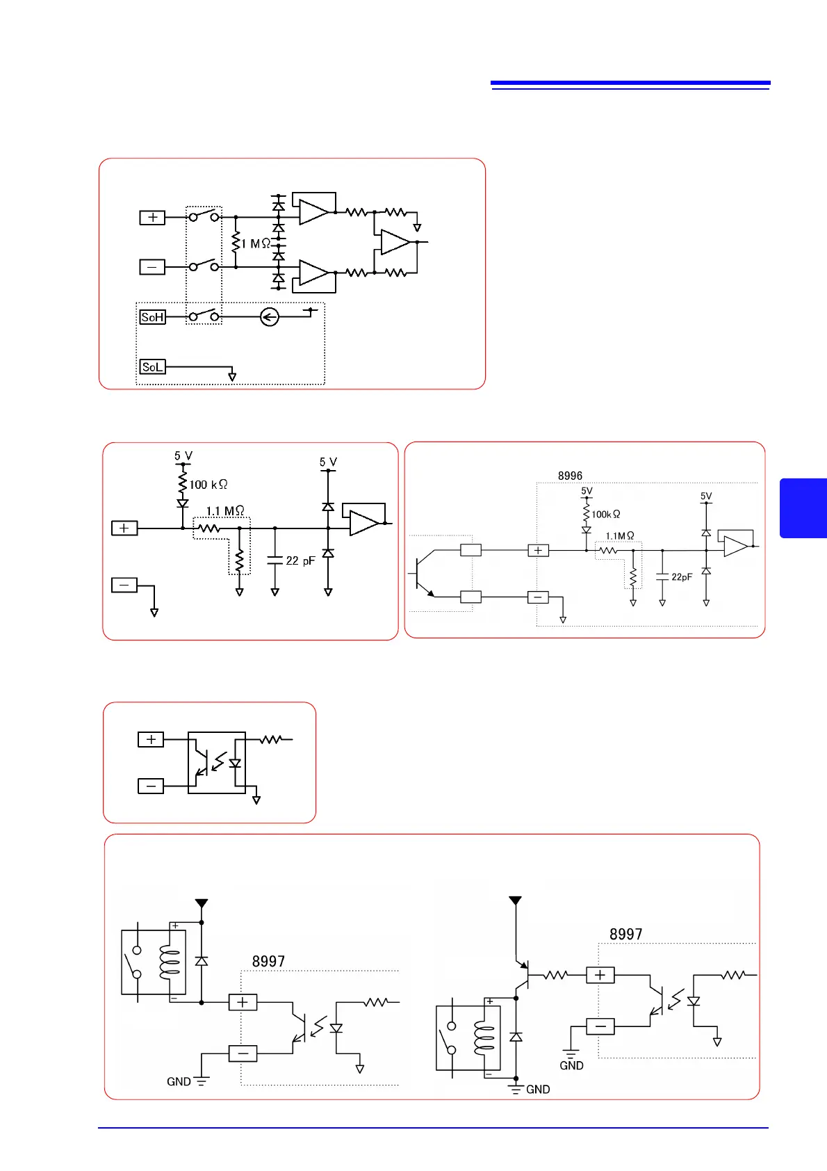
Units' circuit architecture
Model 8948 Voltage/Temp Unit and 8949 Universal Unit Input Circuit Diagram
Model 8996 Digital/Pulse Unit Input Circuit Diagram
Model 8997 Alarm Unit Output Circuit Diagram
Channel switching relay
Model 8949 only
1 mA constant current circuit
The SoL terminal is common
for all channels
* 0.047 μF when the chattering prevention filter is on
*
Example connection to PLC output
PLC output (negative
common output)
Example relay connections
(Provide a DC power supply that accom-
modates the relay coil's rated voltage.)
Transistor
Relay
Relay
DC power supply
DC power supply
When the relay coil's rated current is 10 mA or less When the relay coil's rated current is greater than 10 mA
(Provide a DC power supply that accom-
modates the relay coil's rated voltage.)