132
To ensure measurement is performed safely, observe the following precautions.
*1 Between each of the input channels 1 to 5 and the logger main unit, between
each of the input channels 6 to 10 and the logger main unit, between each of
the input channels 11 to 15 and the logger main unit, and between each unit
*2 Between each of the input channels 1 to 5 and each of the input channels 6 to
10, between each of the input channels 6 to 10 and each of the input chan-
nels 11 to 15, and between each of the input channels 1 to 5 and each of the
input channels 11 to 15 (GND is common for each of channels 1 to 5, chan-
nels 6 to 10, and channels 11 to 15)
• The maximum input voltage, maximum rated voltage to earth, and maximum
rated voltage between channels for the input/output terminals of each unit and
the external control input terminals of the 8423 Memory HiLogger main unit are
as shown in the table below. To avoid an electric shock accident or damage to
the instrument, do not input the corresponding voltages or above.
• Channels are isolated by semiconductor relays. Never apply a voltage in
excess of the specifications between channels as doing so could damage the
semiconductor relays by causing them to short out. Exercise particular care
concerning surge protection against lightning and other threats. If the instru-
ment yields erroneous measured values, have it inspected.
• Do not input a voltage that exceeds the measurement range of each range.
Doing so will damage the unit.
• Do not directly input a voltage into the output terminal of the 8997 Alarm Unit.
Doing so will damage the unit.
• The GND of the external control input terminals and the GND of the Memory
HiLogger main unit are not commonly insulated. To avoid damaging the instru-
ment, make sure wiring is done in such a manner that no potential difference
can result between the GND of the external control input terminals and the
GND of the equipment or device to be connected.
Input/Output Terminals
Maximum Input
Voltage
Maximum Rated
Voltage to Earth
Maximum Rated
Voltage between
Channels
Model 8948 Input terminals 100 VDC 600 V AC/DC 200 VDC
Model 8949 Input terminals 60 VDC 600 V AC/DC 120 VDC
Model 8996 Input terminals 50 V DC
600 V AC/DC
*1
33 Vrms
or 70 VDC
*2
Model 8997
Output terminals
-- 600 V AC/DC
33 Vrms
or 70 VDC
External
Control Input
Terminals
SMPL / TRIG
-5 to 10 VDC Not insulated --START
STOP
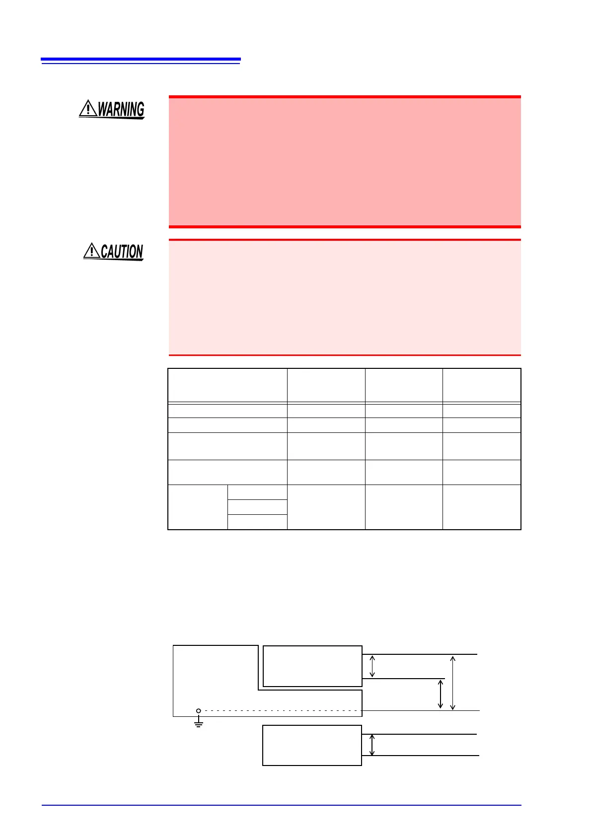
Model 8423 Unit
GND
Maximum Input
Voltage
Maximum
Rated Voltage
to Earth
+
-
CH n
CH m
Maximum Rated Voltage
between Channels
n ≠ m, n, m = 1 to 15
Unit