Operation Manual - STP
Quidway S6500 Series Ethernet Switches Chapter 1 MSTP Region-configuration
Huawei Technologies Proprietary
1-30
Operation Command
Enable/Disable MSTP (packet
receiving/transmitting, event, error)
debugging on the port.
[ undo ] debugging stp [ interface
interface-list ] { packet | event }
Enable event debugging of MSTP [ undo ] debugging stp event
Enable error debugging of MSTP on global
debugging stp global-error
Enable event debugging of MSTP on global
debugging stp global-event
1.4 Typical MSTP Configuration Example
I. Networking requirement
MSTP provides different forwarding paths for packets of different VLANs. The
configurations are as follows: all the switches in the network belong to the same MST
domain, packets of VLAN 10 travels along instance 1, packets of VLAN 30 travels along
instance 3, packets of VLAN 40 travels along instance 0.
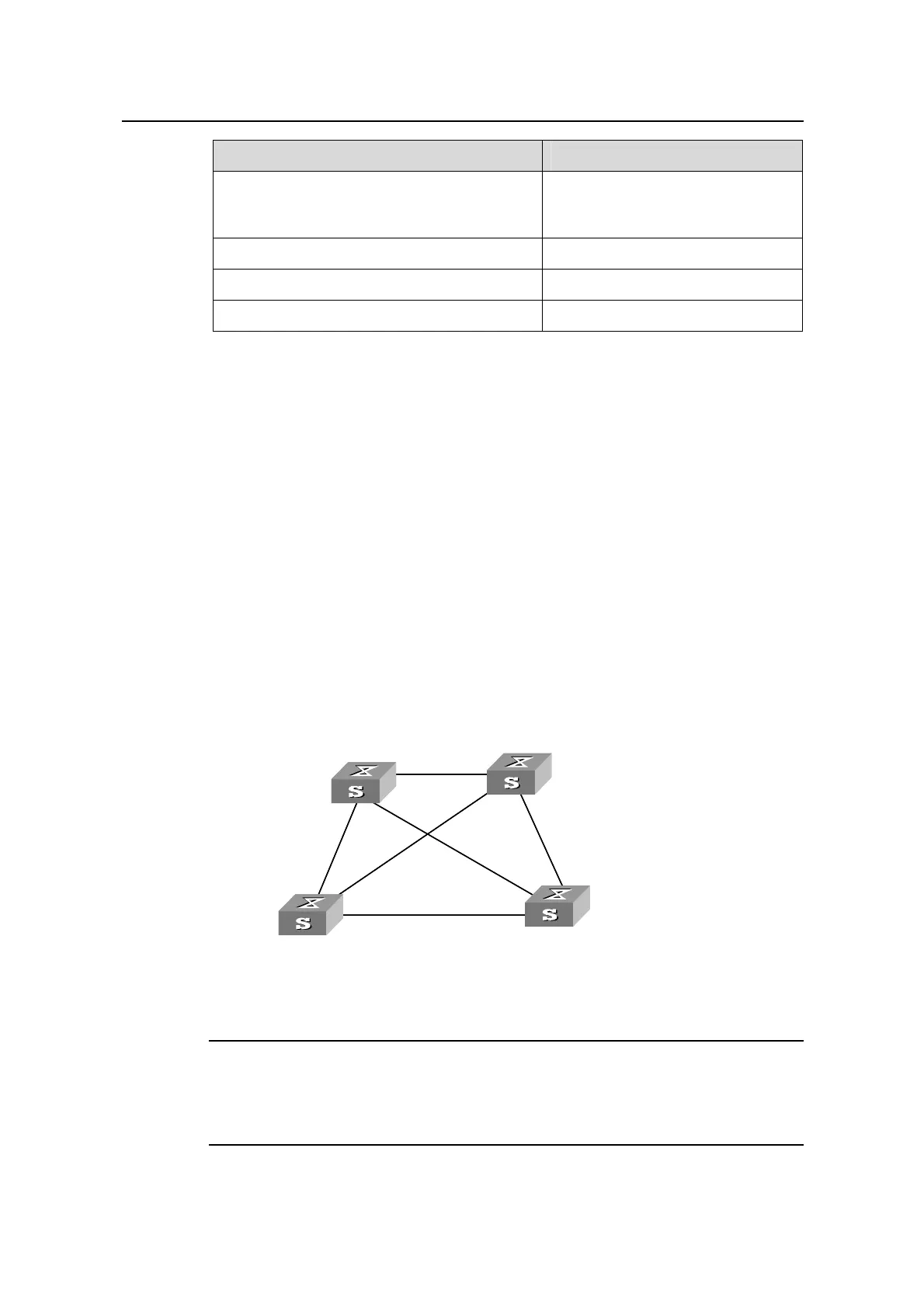
In the following network diagram, Switch A and Switch B are devices of the distribution
layer, Switch C and Switch D are devices of the access layer. VLAN 10 and 30 function
at the distribution and access layers, and VLAN 40 functions at the access layer only.
So the root of instance 1 can be configured as Switch A, root of instance 3 can be
Switch B, and root of instance 4 can be Switch C.
II. Network diagram
Switch A
Switch C
Switch B
Switch D
Permit :
VLAN 10, 20
Permit :
VLAN 10, 20
Permit :
VLAN 20, 30
Permit :
VLAN 20, 30
Permit :all VLAN
Permit :VLAN 20, 40
Switch A
Switch C
Switch B
Switch D
Permit :
VLAN 10, 20
Permit :
VLAN 10, 20
Permit :
VLAN 20, 30
Permit :
VLAN 20, 30
Permit :all VLAN
Permit :VLAN 20, 40
Figure 1-6 MSTP network diagram
Note:
The explanations on the above figure which goes like ”permit: XXXX” means that
packets of these VLANs are permitted to pass.
 Loading...


