Operation Manual - STP
Quidway S6500 Series Ethernet Switches Chapter 2 BPDU Tunnel Configuration
Huawei Technologies Proprietary
2-3
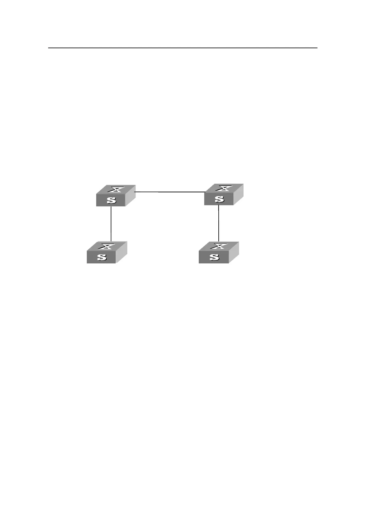
2.3 BPDU Tunnel Configuration Example
I. Network requirements
z The S6500 Series Ethernet Switches are used as the access devices of the
operator’s network, that is, Switch C and Switch D in the following figure.
z The S2000 Series Ethernet Switches are used as the access devices of the user
network, that is, Switch A and Switch B in the following figure.
z Switch C and Switch D connect to each other through trunk port, enabling the
BPDU Tunnel function in system view, and implementing the transparent
transmission between user network and operator’s network.
II. Networking diagram
E 3/0/1
Switch C
Switch A
E 4/0/1
E 0/1
Switch D
Switch B
E 3/0/2
E 0/1
E 4/0/2
E 3/0/1
Switch C
Switch A
E 4/0/1
E 0/1
Switch D
Switch B
E 3/0/2
E 0/1
E 4/0/2
Figure 2-2 Network diagram for BPDU Tunnel configuration
III. Configuration procedures
1) Configure Switch A
# Enable RSTP on the device.
[Quidway] stp enable
# Add port Ethernet 0/1 into VLAN 10.
[Quidway] vlan 10
[Quidway-Vlan10] port Ethernet 0/1
2) Configure Switch B
# Enable RSTP on the device.
[Quidway] stp enable
# Add port Ethernet 0/1 into VLAN 10.
[Quidway] vlan 10
[Quidway-Vlan10] port Ethernet 0/1
 Loading...


