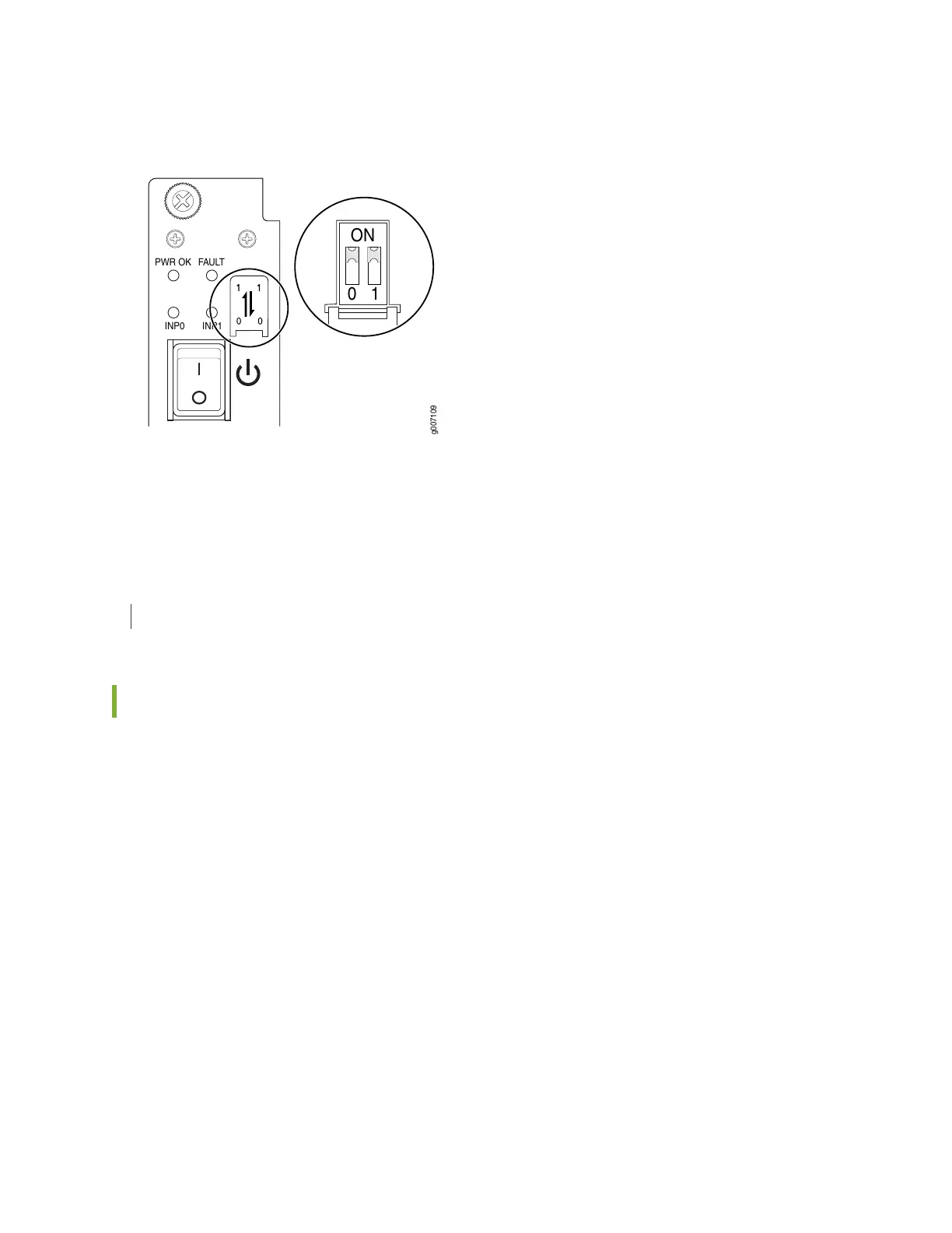
Figure 45: Selecting the Input Feed on the AC Power Supply Module
PWR OK
FAULT
INP0
INP1
10
ON
g007109
A PSM failure triggers the alarm LED on the craft interface. For information about connecting to AC power
sources, see “MX2000 AC Power System Electrical Specifications” on page 179.
RELATED DOCUMENTATION
MX2020 AC Power Supply Module LEDs | 106
MX2020 AC Power Supply Module LEDs
Each AC PSM faceplate contains four LEDs. These LEDs are described in Table 29 on page 107. There are
a total of eighteen bicolor LEDs located in the craft interface, and are labeled 0 through 8 for the bottom
nine PSMs, and 9 through 17 for the top nine PSMs. Both feeds are alive during operation, but only one
feed provides current. In addition, a PSM failure triggers the red alarm LED on the craft interface.
106