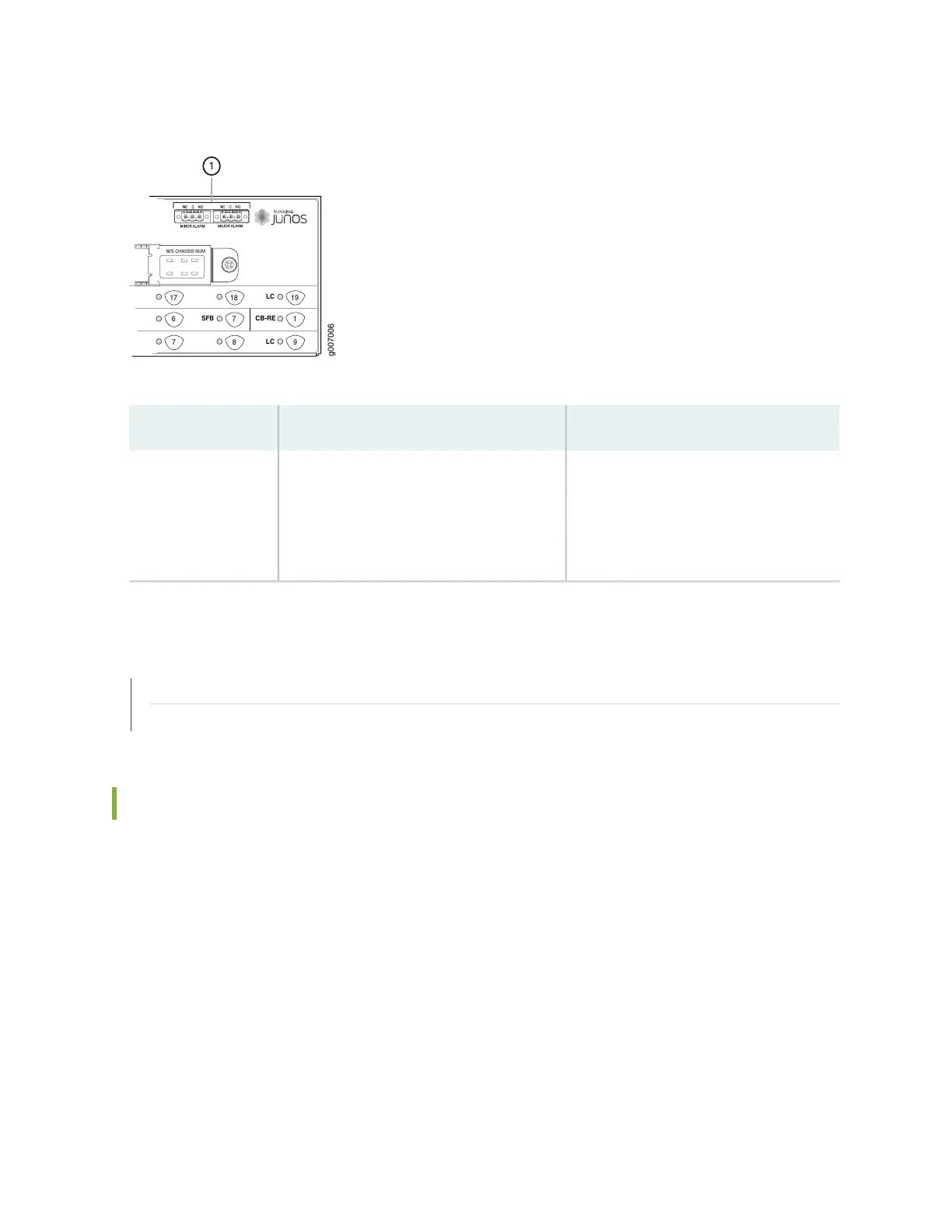
Figure 13: Alarm Relay Contacts
M/S CHASSIS NUM
17
6
7
18
7
8
19
1
9
LC
CB-RE
LC
SFB
g007006
1
Table 11: Alarm Relay Contacts
DescriptionLabelFunction No.
The alarm relays consist of three terminal
contacts with a normal closed (NC),
common (C), and normal open (NO) relays
that signal a minor or major alarm when
broken.
MINOR ALARM–[NC C NO]
MAJOR ALARM–[NC C NO]
1
RELATED DOCUMENTATION
Disconnecting the Alarm Relay Wires from the MX2020 Craft Interface | 343
Connecting the Alarm Relay Wires to the MX2020 Craft Interface | 342
MX2020 Alarm LEDs and Alarm Cutoff/Lamp Test Button
Two large alarm LEDs are located at the upper right of the craft interface. When lit, the circular red LED
indicates a critical condition that can result in a system shutdown. A lit triangular yellow LED indicates a
less severe condition that requires monitoring or maintenance. Both LEDs can be lit simultaneously.
A condition that causes an LED to light also activates the corresponding alarm relay contact on the craft
interface.
To deactivate red and yellow alarms, press the button labeled ACO/LT (for “alarm cutoff/lamp test”), which
is located to the right of the alarm LEDs. Deactivating an alarm turns off both LEDs and deactivates the
device attached to the corresponding alarm relay contact on the craft interface.
Table 12 on page 35 describes the alarm LEDs and alarm cutoff button in more detail.
34