Installing MX2020 AC Power Supply Modules
To install an MX2020 AC PSM:
1. Verify that the power switch on the PSM is in the off (O) position.
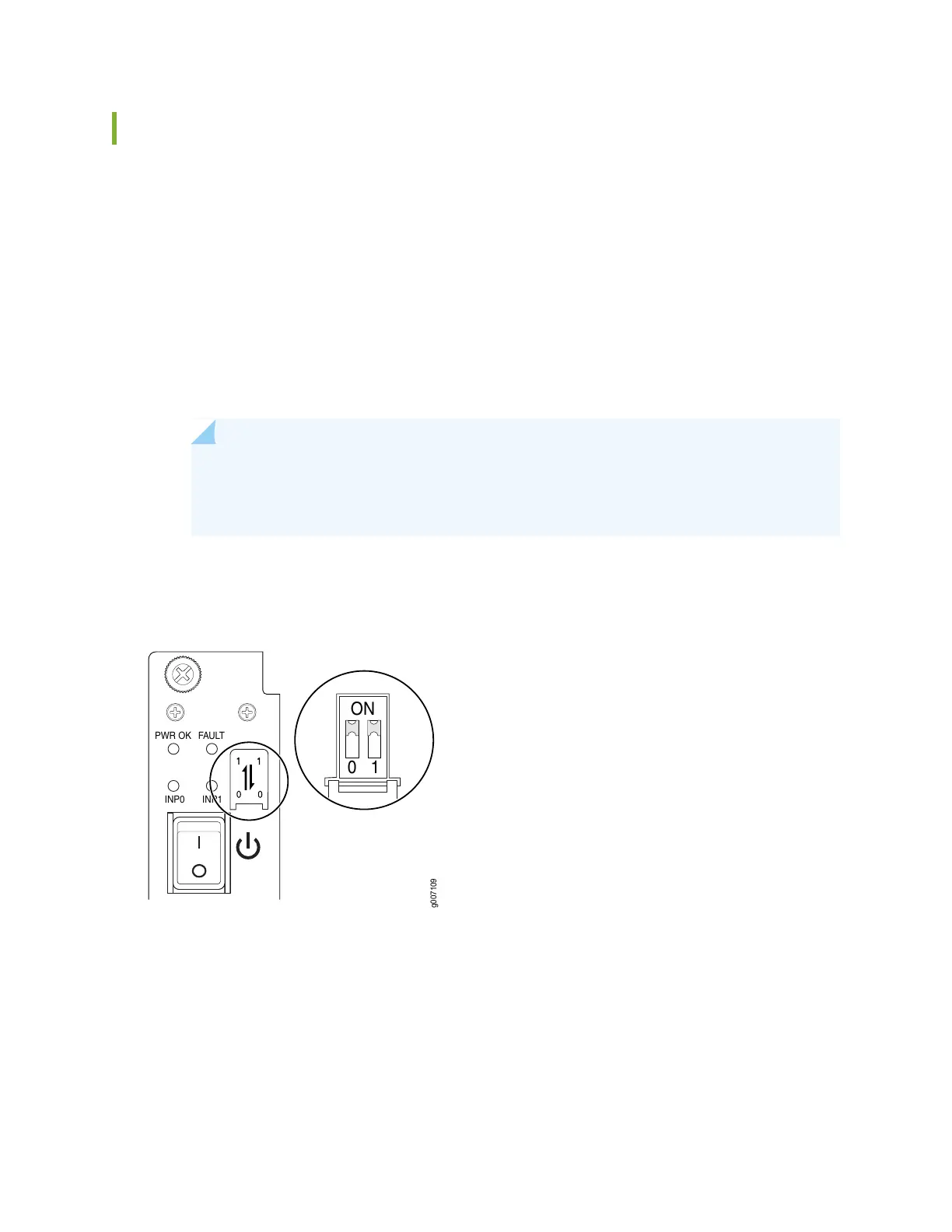
2. On the PSM, slide the plastic cover away from the input mode switch to expose the dual DIP switches.
Move the input mode DIP switch 0 (left switch) to the ON position for the bottom feed INP0 (expected
to be connected), and DIP switch 1 (right switch) to the ON position for the top feed INP1 (expected
to be connected). If both DIP switches 0 and 1 are turned to the ON position, then both top and bottom
feeds are expected to be connected (see Figure 131 on page 307).
In addition, a PSM failure triggers the alarm LED on the craft interface.
NOTE: The DIP switches are only used to indicate presence of a feed. If both feeds are
present, power is always drawn from feed 0. Power will be drawn from feed 1 only if feed
0 fails.
Figure 131: Selecting AC Power Subsystem Feed Redundancy
PWR OK
FAULT
INP0
INP1
10
ON
g007109
3. Using both hands, grasp the handle and slide the PSM straight into the chassis until the PSM is fully
seated in the chassis slot. Tighten the two captive screws (see Figure 132 on page 308). Apply between
10 lb-in. (1.13 Nm) to 12 lb-in. (1.35 Nm) of torque to each screw. Do not overtighten the screws.
307