3. Plug the terminal block into the relay contact, and use a 2.5 mm flat-blade screwdriver to tighten the
screws on the face of the block.
4. Attach the other end of the wires to the external device.
To attach a reporting device for the other kind of alarm, repeat the procedure.
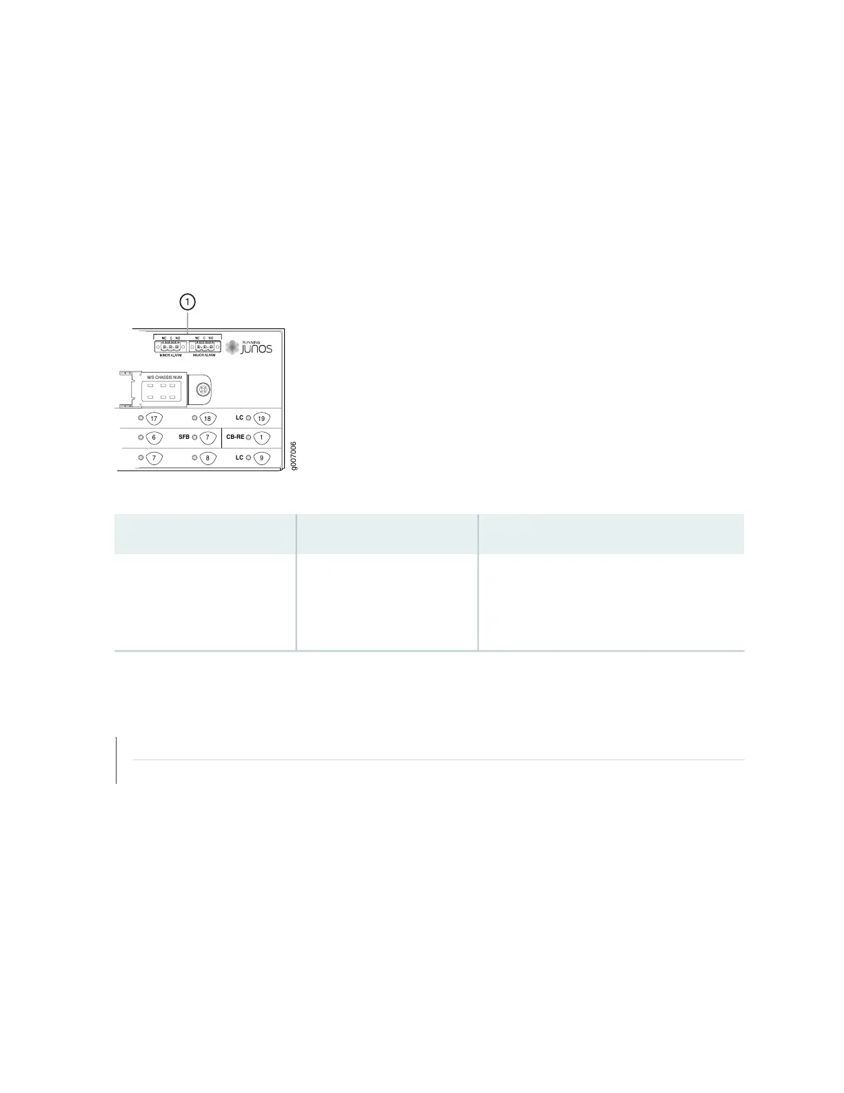
Figure 157: Alarm Relay Contacts
M/S CHASSIS NUM
17
6
7
18
7
8
19
1
9
LC
CB-RE
LC
SFB
g007006
1
Table 95: Alarm Relay Contacts
DescriptionLabelFunction No.
The alarm relays consist of three terminal
contacts with a normal closed (NC), common
(C), and normal open (NO) relays that signal a
minor or major alarm when broken.
MINOR ALARM—[NC C NO]
MAJOR ALARM—[NC C NO]
1
RELATED DOCUMENTATION
Connecting the MX2020 Router to a Console or Auxiliary Device | 334
Connecting the MX2020 Router to a Network for Out-of-Band Management | 333
341