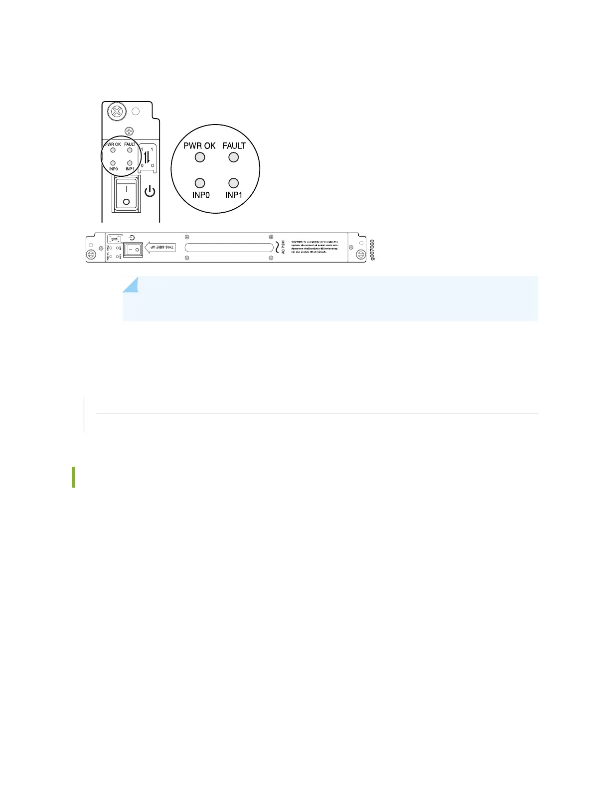
Figure 133: MX2020 AC Power Supply Module Front View
NOTE: Each PSM slot not occupied by a AC PSM must be covered by a PSM blank panel.
RELATED DOCUMENTATION
Preventing Electrostatic Discharge Damage to an MX2020 Router
Powering On the AC-Powered MX2020 Router
Installing MX2000 Router DC Power Supply Modules (-48 V)
To install an MX2000 DC PSM (-48 V):
1. Verify that the power switches on all PSMs are in the off (O) position.
2. On the PSM, slide the plastic cover away from the input mode switch to expose the dual DIP switches.
Move the input mode DIP switch 0 (left switch) to the ON position for the bottom feed INP0 (expected
to be connected), and DIP switch 1 (right switch) to the ON position for the top feed INP1 (expected
to be connected). If both DIP switches 0 and 1 are turned to the ON position, then both top and bottom
feeds are expected to be connected, (see Figure 134 on page 310).
In addition, a PSM failure triggers the alarm LED on the craft interface.
309