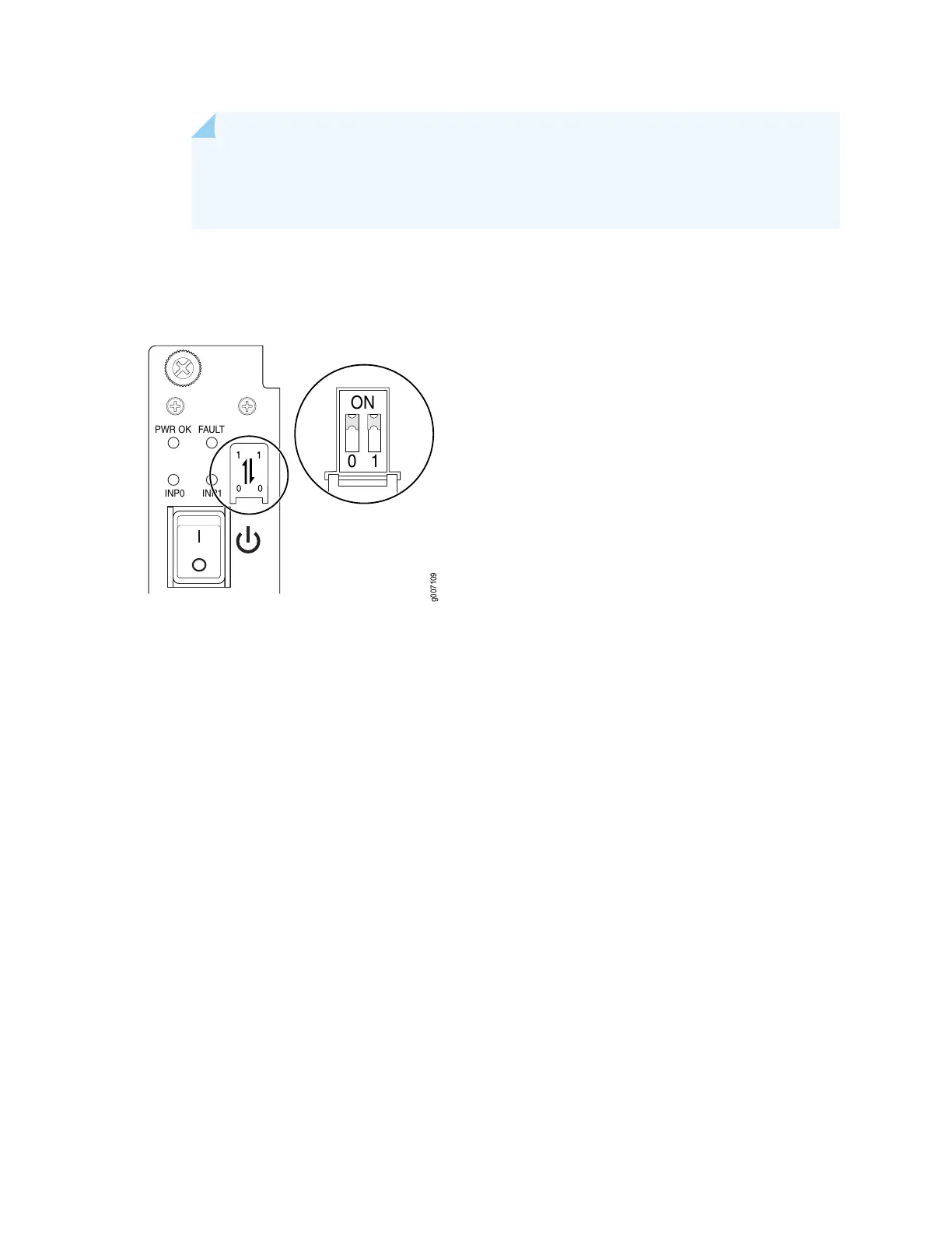
NOTE: The DIP switches are only used to indicate presence of a feed. If both feeds are
present, power is always drawn from feed 0. Power will be drawn from feed 1 only if feed
0 fails.
Figure 134: Selecting DC Power Subsystem Feed Redundancy
PWR OK
FAULT
INP0
INP1
10
ON
g007109
3. Using both hands, grasp the handle and slide the PSM straight into the chassis until the PSM is fully
seated in the chassis slot. Tighten the two captive screws (see Figure 135 on page 311 (MX2020) and
Figure 136 on page 311) (MX2010), or Figure 137 on page 312 (MX2008). Apply between 10 lb-in.
(1.13 Nm) to 12 lb-in. (1.35 Nm) of torque to each screw. Do not overtighten the screws.
310
 Loading...


