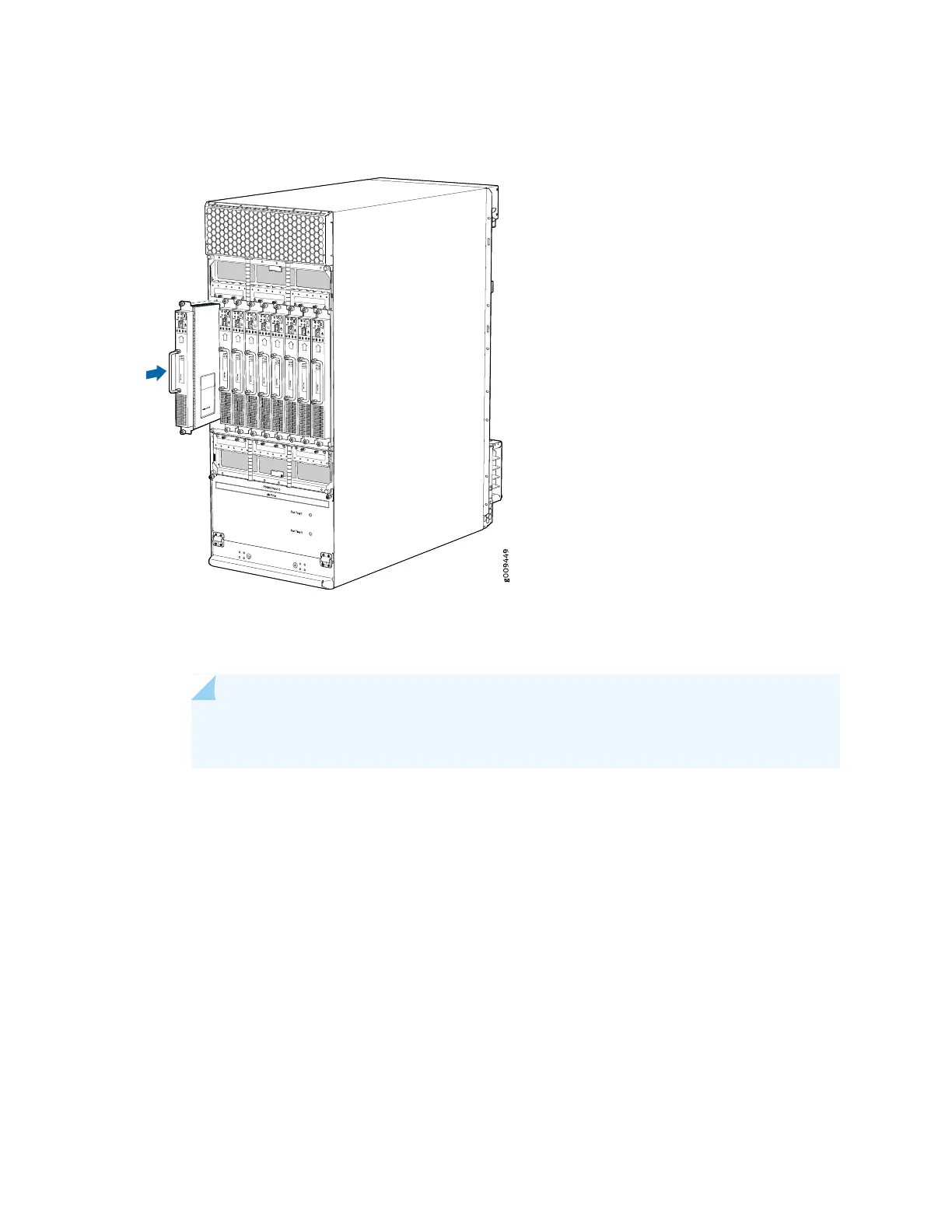
Figure 137: Installing an MX2008 Router DC Power Supply Module
4. Verify that the INP0 and/or INP1 LEDs on the PSM are lit green steadily (see Figure 138 on page 313).
NOTE: If you are connecting two feeds, INP0 and INP1, both LEDs on the PSM will be
lit green steadily.
5. Attach an electrostatic discharge (ESD) grounding strap to your bare wrist, and connect the strap to
one of the ESD points on the chassis.
6. Move the switch to the on (|) position.
7. Verify that the PWR OK LED is lit green steadily. See “MX2020 DC and Power Supply Module LEDs”
on page 117, MX2010 DC Power Supply Module LEDs, or MX2008 DC Power Supply Module LEDs for
information on PSM LED behavior.
8. Repeat Steps 1 through 7 for installing PSMs in slots 0, 1, and 2, where required.
312