Connecting the Alarm Relay Wires to the MX2020 Craft Interface
To connect the alarm relay wires between a router and an alarm-reporting device (see
Figure 158 on page 342):
1. Prepare the required length of replacement wire with gauge between 28 AWG and 14 AWG (0.08 and
2.08 mm
2
).
2. Insert the replacement wires into the slots in the front of the block (see Table 96 on page 342). Use a
2.5 mm flat-blade screwdriver to tighten the screws and secure the wire.
3. Attach an electrostatic discharge (ESD) grounding strap to your bare wrist, and connect the strap to
one of the ESD points on the chassis.
4. Plug the terminal block into the relay contact, and use a 2.5 mm flat-blade screwdriver to tighten the
screws on the face of the block.
5. Attach the other end of the wires to the external device.
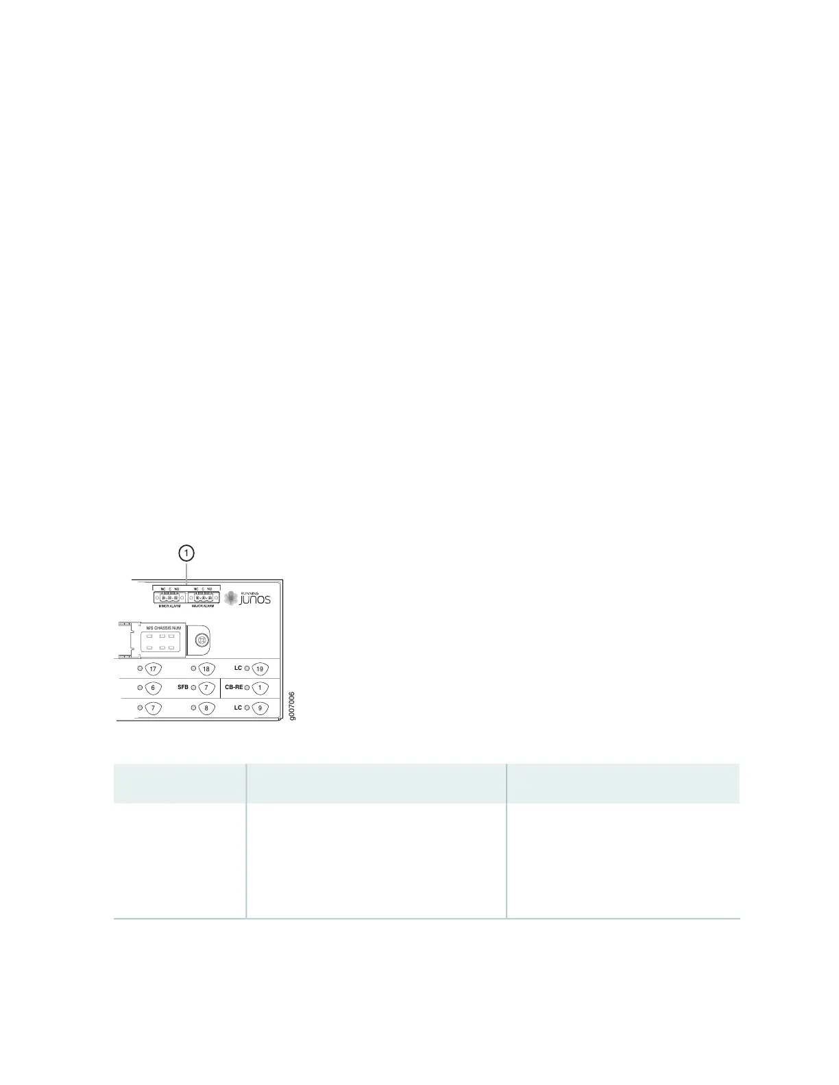
Figure 255: Alarm Relay Contacts
M/S CHASSIS NUM
17
6
7
18
7
8
19
1
9
LC
CB-RE
LC
SFB
g007006
1
Table 102: Connecting Alarm Relay Contacts
DescriptionLabelFunction No.
The alarm relays consist of three terminal
contacts with a normal closed (NC),
common (C), and normal open (NO) relays
that signal a minor or major alarm when
broken.
MINOR ALARM—[NC C NO]
MAJOR ALARM—[NC C NO]
1
588