3. Using a 2.5 mm flat-blade screwdriver, loosen the small screws on the face of the terminal block and
remove the block from the relay contact.
4. Using the 2.5 mm flat-blade screwdriver, loosen the small screws on the side of the terminal block.
Remove existing wires from the slots in the front of the block (see Table 97 on page 344).
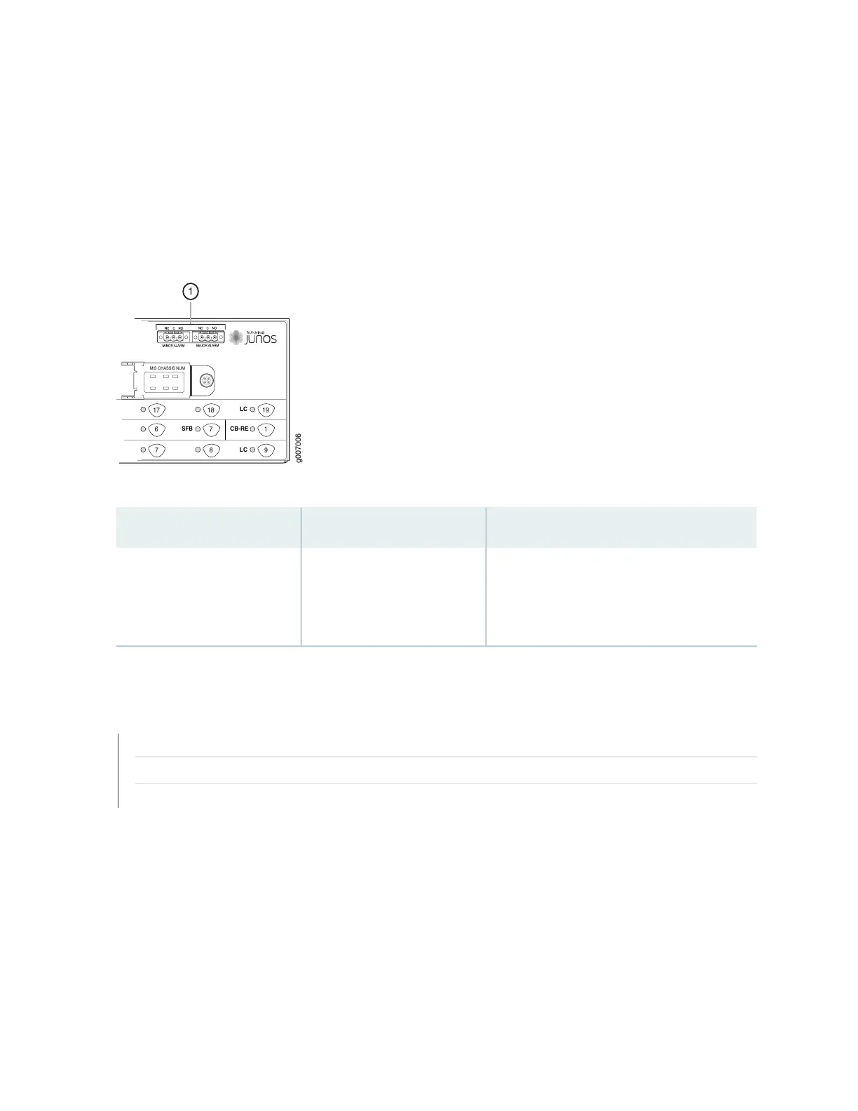
Figure 254: Alarm Relay Contacts
M/S CHASSIS NUM
17
6
7
18
7
8
19
1
9
LC
CB-RE
LC
SFB
g007006
1
Table 101: Alarm Relay Contacts on the Craft Interface
DescriptionLabelFunction No.
The alarm relays consist of three terminal
contacts with a normal closed (NC), common
(C), and normal open (NO) relays that signal a
minor or major alarm when broken.
MINOR ALARM—[NC C NO]
MAJOR ALARM—[NC C NO]
1
SEE ALSO
Installing the MX2020 Craft Interface | 582
Removing the MX2020 Craft Interface | 581
Maintaining and Verifying the Status of the MX2020 Craft Interface | 589
587