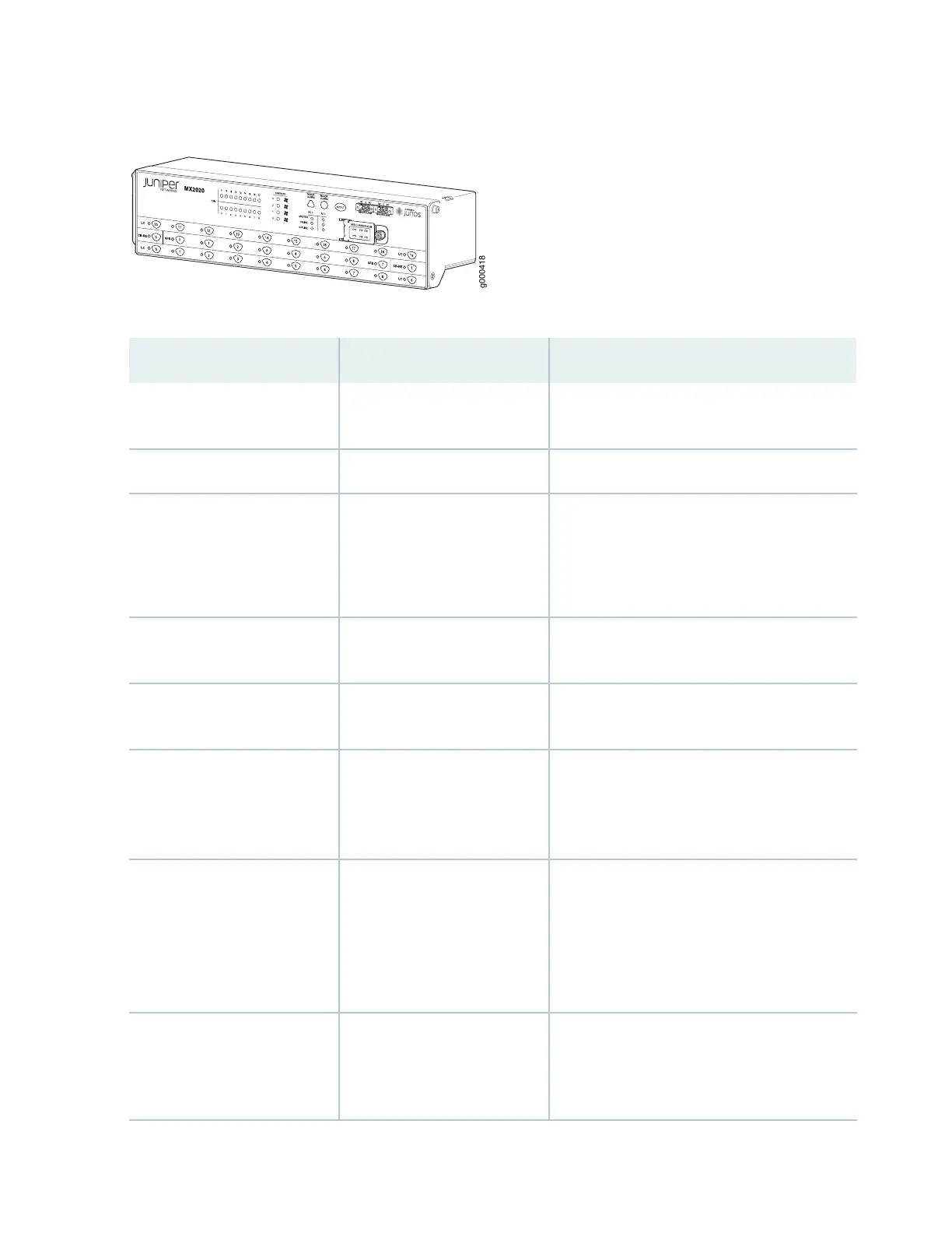
Figure 12: Extended Craft Interface
Table 10: Craft Interface LEDs, Buttons, and Connectors
DescriptionLabelFunction No.
Status LEDs for PSMs 0 through 8 and 9 through
17
PSM1
Status LEDs for fan trays 0 through 3FANTRAYS2
Two sets of status LEDs per host subsystem.
There are three LEDs per Routing Engine.
RE0 (MASTER, ONLINE, and
OFFLINE)
RE1 (MASTER, ONLINE, and
OFFLINE)
3
Minor Alarm LED for monitoring or maintaining
the MX2020
MINOR ALARM4
Major Alarm LED for critical conditions, that can
result in system shutdown
MAJOR ALARM5
Alarm Cutoff/ Lamp Test Button. Turns off both
minor and major alarms and deactivates the
device attached to the corresponding alarm relay
contact on the craft interface
ACO/LT6
Chassis ID and Standalone Dial. These two dials
are used. One dial is used to indicate the chassis
number for multi-chassis configurations. The
second dial is used to indicate whether the
chassis is operating in standalone mode or as
part of a multi-chassis system.
M/S CHASSIS NUM7
Two sets of alarm terminal contacts. Each
consisting of normal open and normal closed
relays that signal a minor or major alarm when
broken.
MINOR ALARM–[NC C NO]
MAJOR ALARM–[NC C NO]
8
32