Gocator Line Profile Sensors: User Manual
Gocator Web Interface • 128
height.
6. Click the tracking window's Select button.
7. Resize the tracking window shown in the data viewer.
Only the height of the window is required. You can move the position of the tracking window to cover a
live profile to help adjust the window height.
8. Edit the Search Threshold setting.
The search threshold defines the minimum percentage of the points detected across the profile for the
laser to be considered tracked. If the number of points falls below this percentage, tracking is lost, and
the sensor searches for the laser line using the full active area.
9. Click the Save button in the Sensor panel.
10. Save the job in the Toolbar by clicking the Save button .
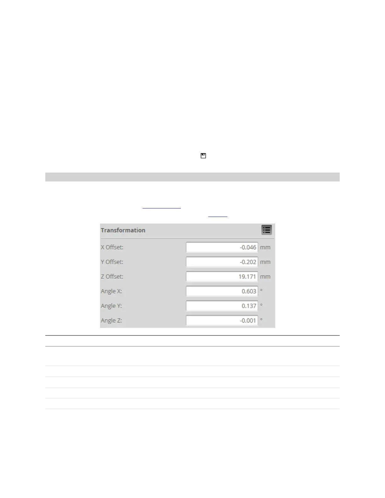
Transformations
The transformation settings determine how data is converted from sensor coordinates to system
coordinates (for an overview on coordinate systems, see Coordinate Systems on page 58). Typically,
transformations are set when you align a sensor. However, you can also manually set values using the
Transformations section of the Active Area tab on the Sensor panel.
Parameter Description
X Offset
Specifies the shift along the X axis. With Normal orientation, a positive value shifts the data to the
right. With Reverse orientation, a positive value shifts the data to the left.
Y Offset Specifies the shift along the Y axis.
Z Offset
Specifies the shift along the Z axis. A positive value shifts the data toward the sensor.
Angle X Specifies the tilt around the X axis.
Angle Y Specifies the tilt around the Y axis.
Angle Z Specifies the tilt around the Z axis.
When applying the transformations, the object is first rotated around X, then Y, and then Z, and then the
offsets are applied.
 Loading...