Gocator Line Profile Sensors: User Manual
Specifications • 770
Active High
If the supplied voltage is greater than 24 V, connect an external resistor in series to the positive.The
resistor value should be R = [(Vin-1.2V)/10mA]-680.
Active Low
To assert the signal, the digital input voltage should be set to draw a current of 3 mA to 40 mA from the
positive pin. The current that passes through the positive pin is I = (Vin – 1.2 – Vdata) / 680. To reduce
noise sensitivity, we recommend leaving a 20% margin for current variation (i.e., uses a digital input
voltage that draws 4mA to 25mA).
Function Pins Min Voltage Max Voltage Min Current Max Current Min Pulse Width
Trigger_in D, H 3.3 V 24 V 3 mA 40 mA 20 µs
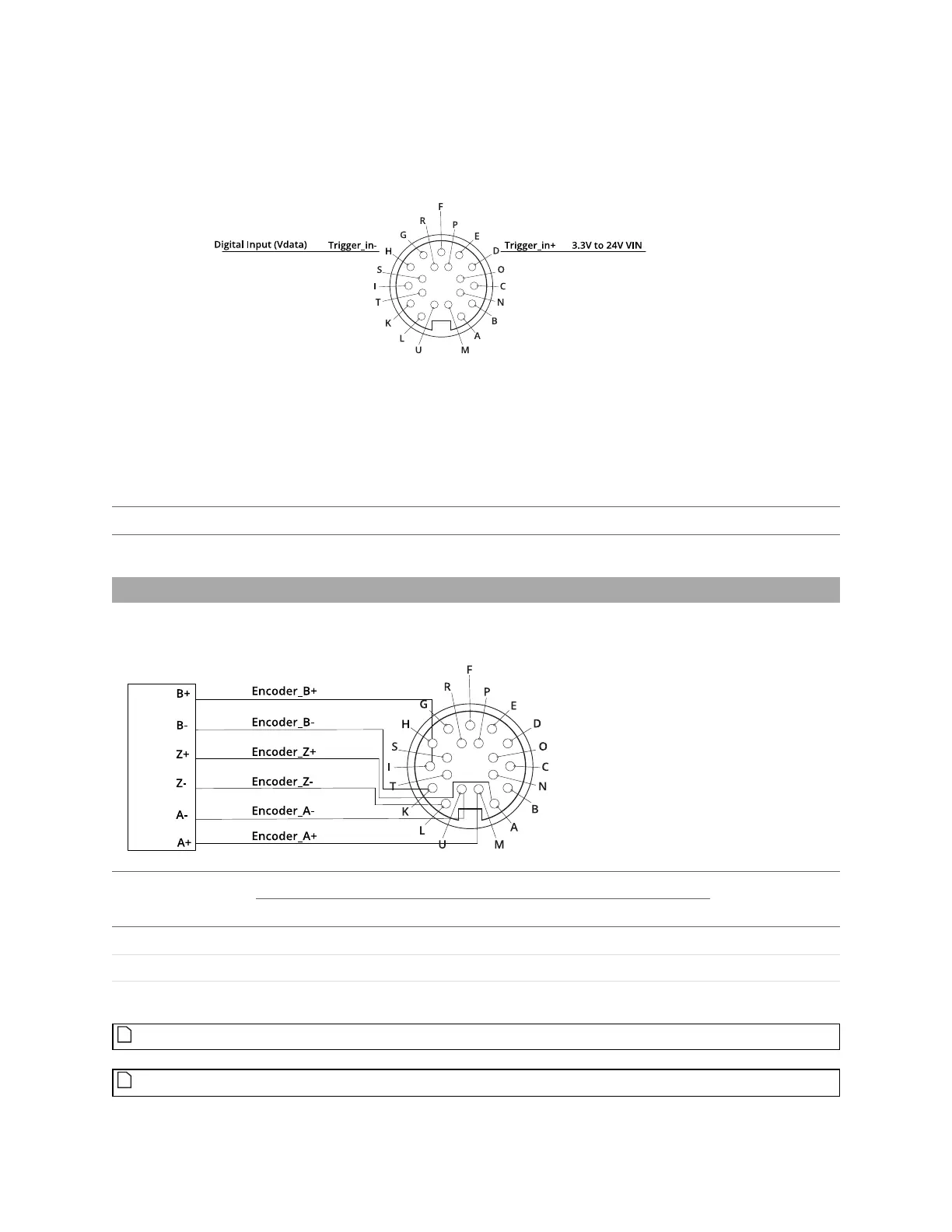
Encoder Input
Encoder input is provided by an external encoder and consists of three RS-485 signals. These signals are
connected to Encoder_A, Encoder_B, and Encoder_Z.
Function Pins
Common Mode Voltage Differential Threshold Voltage
Max Data Rate
Min Max Min Typ Max
Encoder_A M, U -7 V 12 V -200 mV -125 mV -50 mV 1 MHz
Encoder_B I, K -7 V 12 V -200 mV -125 mV -50 mV 1 MHz
Encoder_Z A, L -7 V 12 V -200 mV -125 mV -50 mV 1 MHz
Gocator only supports differential RS485 signalling. Both + and - signals must be connected.
Encoders are normally specified in pulses per revolution, where each pulse is made up of the
 Loading...

