Gocator Line Profile Sensors: User Manual
How Gocator Works • 62
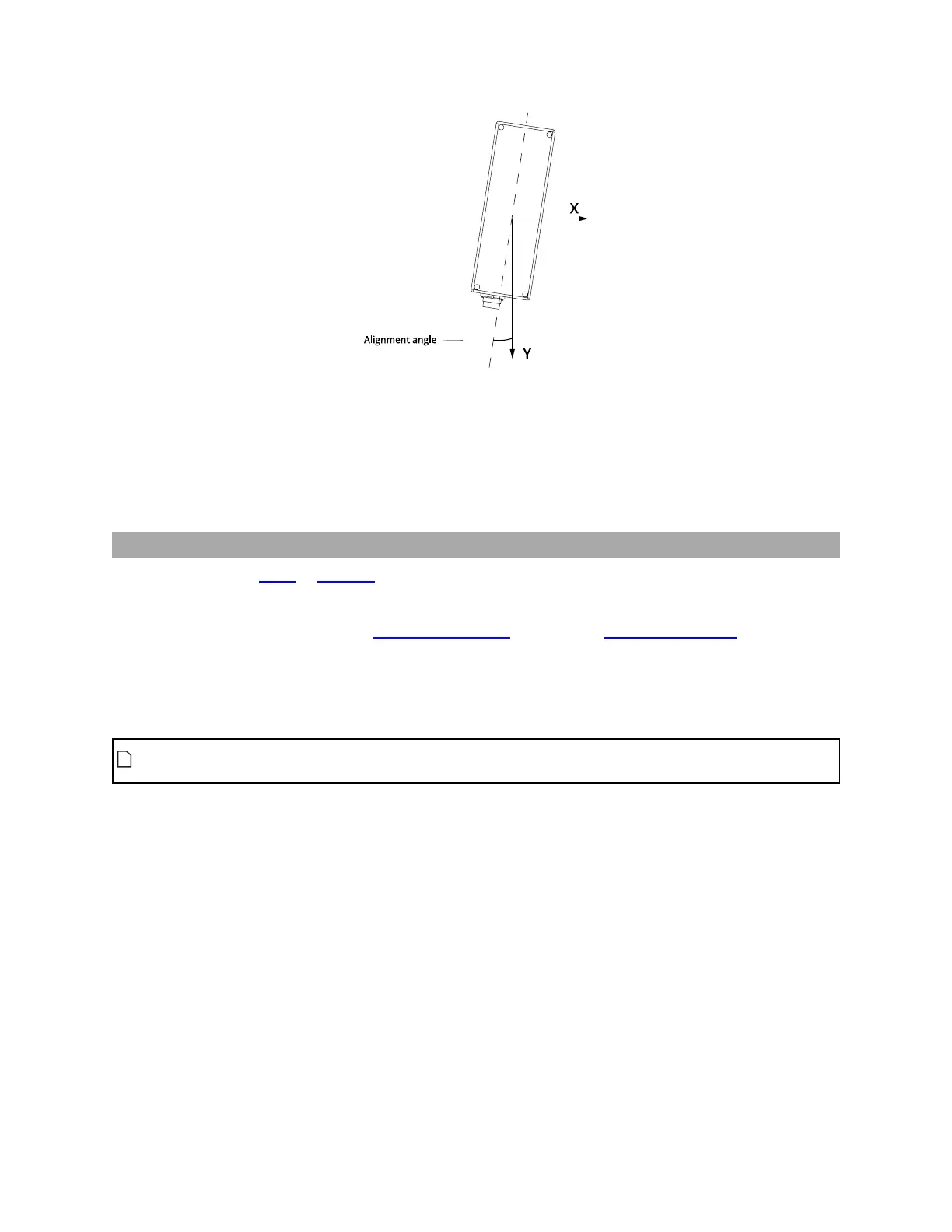
Gocator 2130/2330 sensor:Z Angle
X angle is positive when rotating from positive Y to positive Z. Z angle is positive when rotating from
positive X to positive Y.
When applying the transformations, the object is first rotated around X, then Y, and then Z, and then the
offsets are applied.
Part and Section Coordinates
When you work with parts or sections extracted from scan data, a different coordinate system is
available.
Part data can be expressed in aligned system coordinates or unaligned sensor coordinates. But part data
can also be represented in part coordinates: data and measurement results are in a coordinate system
that places the X and Yorigins at the center of the part. The Z origin is at the surface surrounding the
alignment target (if the sensor or system has been aligned) or in the center of the center of the
measurement range (if the sensor or system has not been aligned).
The Frame of Reference setting, in the Part Detection panel on the Scan page, controls
whether part data is recorded using sensor/system coordinates or part coordinates.
 Loading...