Gocator Line Profile Sensors: User Manual
Gocator Web Interface • 340
Parameter Description
X Angle
Y Angle
The X and Yangles you must specify when Tilt Correction is set to Custom.
You can use the Surface Plane tool's XAngle and Y Angle measurements to get the angle of the
surrounding surface, and then copy those measurement's values to the X Angle and Y Angle
parameters of this tool. For more information, see Plane.
Filters The filters that are applied to measurement values before they are output. For more
information, see Filters on page 209.
Decision The Max and Min settings define the range that determines whether the measurement tool
sends a pass or fail decision to the output. For more information, see Decisions on page 208.
Anchor Description
X, Y, or Z Lets you choose the X, Y, or Z measurement of another tool
to use as a positional anchor for this tool.
Anchoring
A measurement must be enabled in the other tool for it to be available as an anchor. The anchor
measurement should also be properly configured before using it as an anchor.
For more information on anchoring, see Measurement Anchoring on page 211.
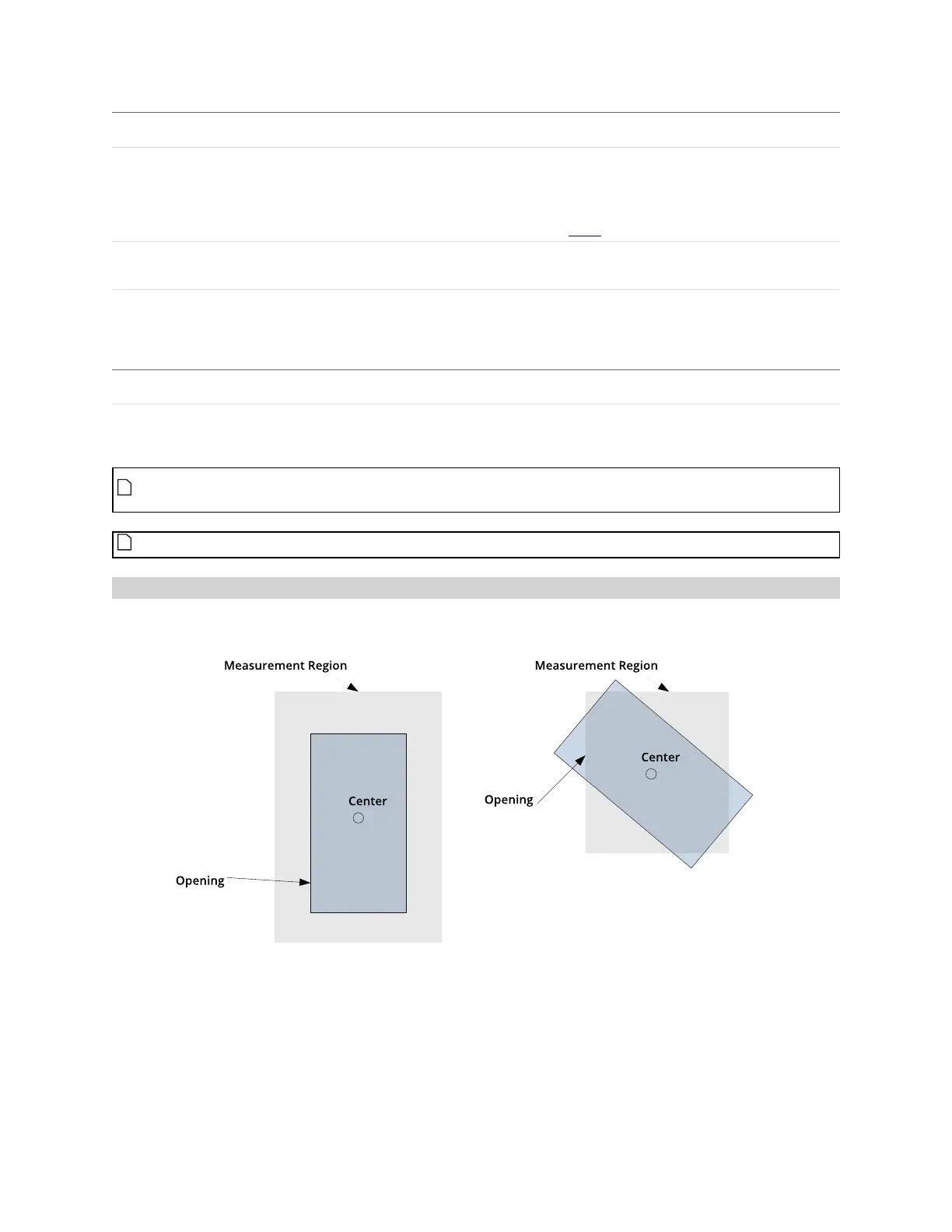
Measurement Region
The center and the two sides and ends of the opening must be within the measurement region, even if
Partial Detection is enabled.
 Loading...