Gocator Line Profile Sensors: User Manual
How Gocator Works • 63
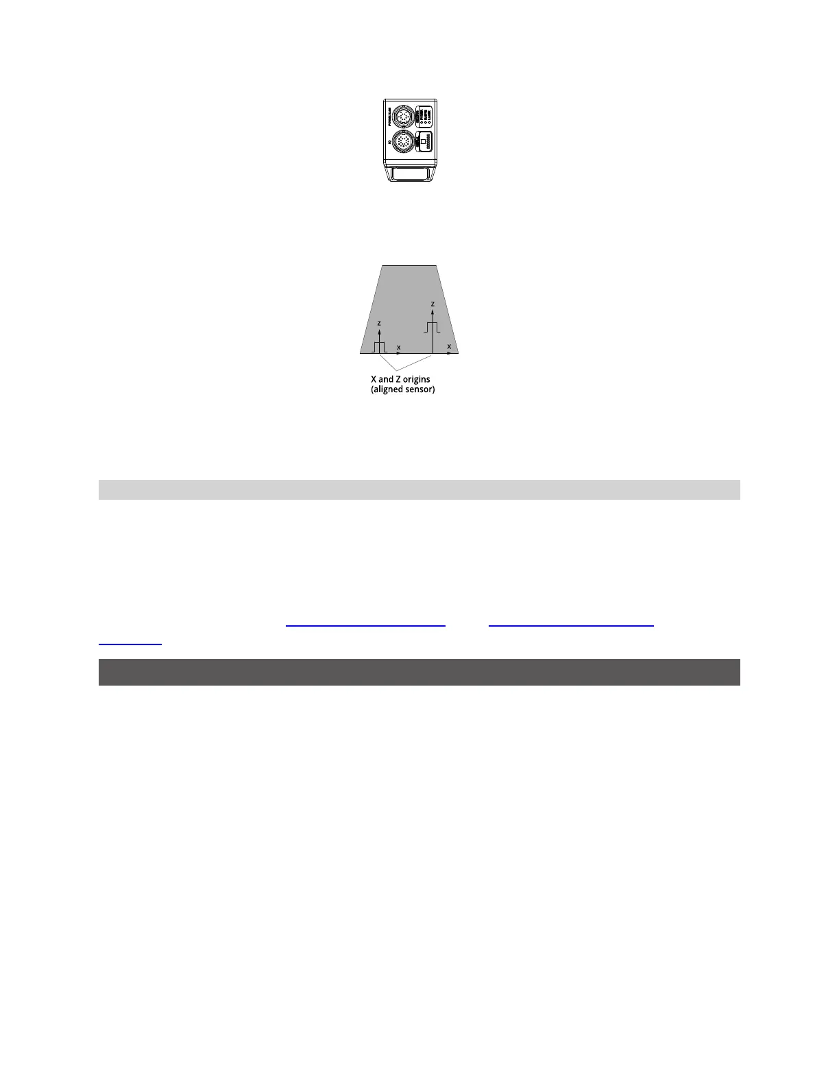
Sections are always represented in a coordinate system similar to part coordinates: the X origin is always
at the center of the extracted profile, and the Z origin is at the bottom of the alignment target (or in the
center of the measurement range if the sensor is unaligned).
Switching between Coordinate Systems
In many situations, when working with part or section data that has been recorded with Frame of
Reference set to Part, it is useful to have access to the "real-world"coordinates, rather than part- or
section-relative coordinates. Gocator provides special "global"measurements, in the Bounding Box
tools, that you can use in Gocator scripts to convert from part or section coordinates to sensor/system
coordinates.
For more information, see the Profile Bounding Box tool or the Surface Bounding Box tool, and the
Script tool.
Resampled Data and Point Cloud Data
The data that a sensor produces in Profile mode is available in two formats: as resampled data and as
point cloud data. The sensor produces resampled data when Uniform Spacing is enabled and produces
point cloud data when Uniform Spacing is disabled. The setting is available in the Scan Mode panel, on
the Scan page.
 Loading...