Gocator Line Profile Sensors: User Manual
Specifications • 773
Master Network Controllers
The following sections provide the specifications of Master network controllers.
For information on maximum external input trigger rates, see Maximum Input Trigger Rate on page 124.
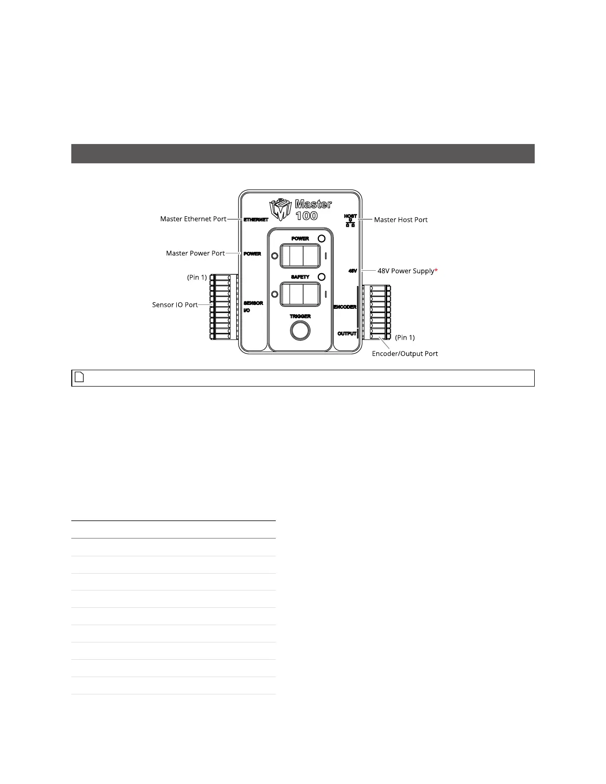
Master 100
The Master 100 accepts connections for power, safety, and encoder, and provides digital output.
*Contact LMI for information regarding this type of power supply.
Connect the Master Power port to the Gocator's Power/LAN connector using the Gocator Power/LAN to
Master cordset. Connect power RJ45 end of the cordset to the Master Power port. The Ethernet RJ45
end of the cordset can be connected directly to the Ethernet switch, or connect to the Master Ethernet
port. If the Master Ethernet port is used, connect the Master Host port to the Ethernet switch with a
CAT5e Ethernet cable.
To use encoder and digital output, wire the Master's Gocator Sensor I/O port to the Gocator IO
connector using the Gocator I/O cordset.
Gocator I/O Pin Master Pin Conductor Color
Encoder_A+ 1 White/Brown & Black
Encoder_A- 2 Brown/Black
Encoder_Z+ 3 White/Green & Black
Encoder_Z- 4 Green/Black
Trigger_in+ 5 Grey
Trigger_in- 6 Pink
Out_1- 7 Blue
Out_1+ 8 Red
Encoder_B+ 11 Black
Encoder_B- 12 Violet
Sensor I/O Port Pins
 Loading...