Gocator Line Profile Sensors: User Manual
Gocator Web Interface • 153
on the detection logic. To do this,
check Enabled in the Part
Detection panel.
To configure surface generation:
1. Go to the Scan page and choose Surface in the Scan Mode panel.
If this mode is not selected, you will not be able to configure surface generation.
2. Expand the Surface Generation panel by clicking on the panel header or the button.
3. Choose an option from the Type drop-down and any additional settings.
See the types and their settings described above.
Part Detection
In Surface mode, a Gocator sensor can analyze scan data to identify discrete objects. Surface
measurements can then be performed on each object. Part detection is configured using the Part
Detection panel on the Scan page.
Part detection must be manually enabled when Type is set to Fixed Length, Variable Length, or
Rotational in the Surface Generation panel. When Type is set to Continuous, part detection is
always enabled.
Part detection can be performed when Source in the Trigger panel is set to Time or Encoder. To use
the Time trigger source, the travel speed must be calibrated. To use the Encoder trigger source, the
encoder resolution must be calibrated. See Aligning Sensors on page 139 for more information.
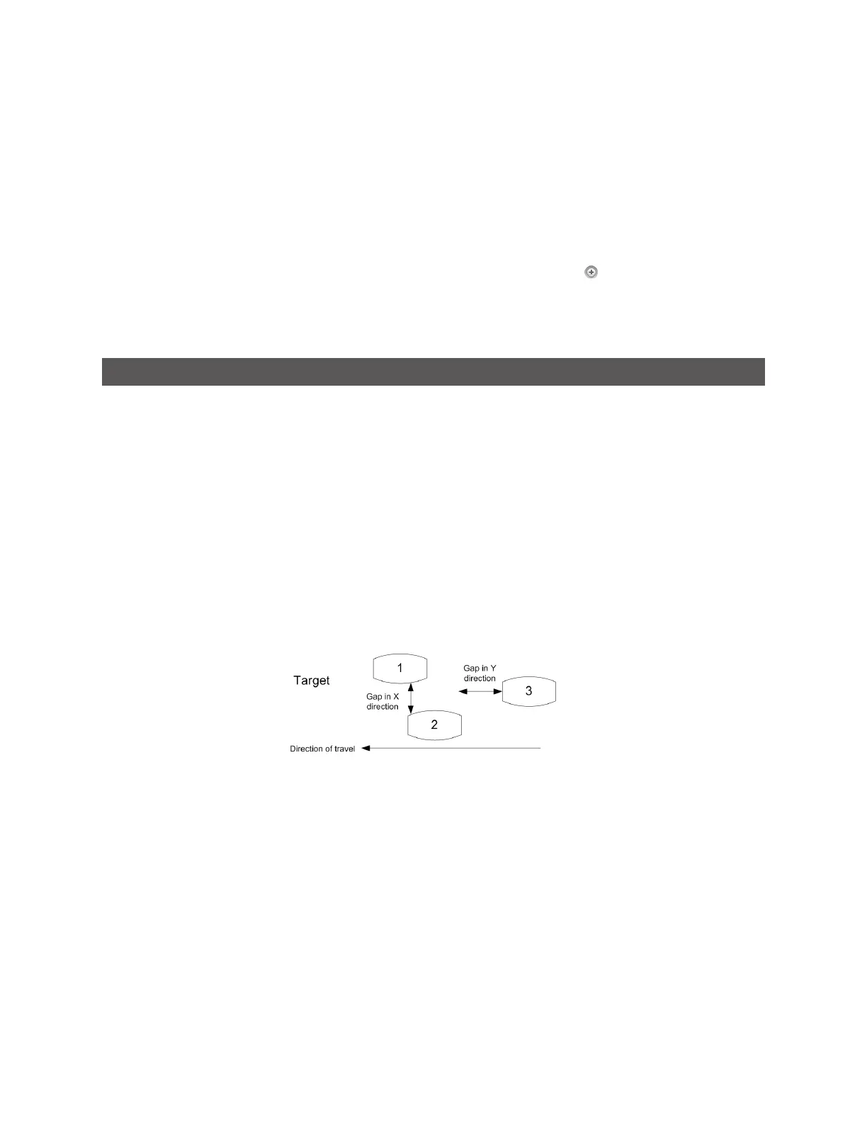
Multiple parts can pass through the laser at the same time and will be individually tracked. Parts can be
separated along the laser line (X axis), in the direction of travel (Y axis), or by gated external input.
 Loading...