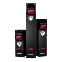
Gocator Line Profile Sensors: User Manual
3
Table of Contents
Copyright 2
Table of Contents 3
Introduction 13
Gocator Overview 14
Safety and Maintenance 15
Laser Safety 15
Laser Classes 16
Precautions and Responsibilities 17
Class 3B Responsibilities 17
Nominal Ocular Hazard Distance (NOHD) 18
Systems Sold or Used in the USA 19
Electrical Safety 20
Heat Warning 20
Handling, Cleaning, and Maintenance 20
Environment and Lighting 21
Getting Started 22
Hardware and Firmware Capabilities 22
Hardware Overview 23
Gocator Sensor 23
Gocator Cordsets 23
Master 100 24
Master 400 / 800 / 1200 / 2400 25
Master 810 / 2410 26
Alignment Targets 28
System Overview 29
Standalone System 29
Dual-Sensor System 30
Multi-Sensor System 31
Installation 33
Mounting 33
Orientations 34
Grounding 36
Gocator 36
Recommended Practices for Cordsets 36
Master Network Controllers 37
Grounding When Using a DIN Rail (Master
810/2410) 38
Additional Grounding Schemes 38
Installing DIN Rail Clips: Master 810 or 2410 38
Configuring Master 810 40
Setting the Divider 41
Encoder Quadrature Frequency 41
Setting the Debounce Period 42
Rut-Scanning System Setup 42
Layout 42
System Setup 43
Software Configuration 43
System Operation 44
Network Setup 45
Client Setup 45
Gocator Setup 48
Running a Standalone Sensor System 48
Running a Dual-Sensor System 49
Next Steps 51
How Gocator Works 53
3D Acquisition 53
Clearance Distance, Field of Viewand
Measurement Range 54
Resolution and Accuracy 55
X Resolution 55
Z Resolution 56
Z Linearity 56
Profile Output 58
Coordinate Systems 58
Sensor Coordinates 58
System Coordinates 59
Part and Section Coordinates 62
Switching between Coordinate Systems 63
Resampled Data and Point Cloud Data 63
Data Generation and Processing 65
Surface Generation 65
Part Detection 65
Sectioning 66
Part Matching 66
Measurement 67
Tool Chaining 67
Anchoring Measurements 68
Geometric Features 70
Tool Data 73
Output and Digital Tracking 77
Gocator Web Interface 79
Browser Compatibility 79
 Loading...

