Gocator Line Profile Sensors: User Manual
Specifications • 769
Digital outputs cannot be used when taking scans using the Snapshot button, which takes a
single scan and is typically used to test measurement tool settings. Digital outputs can only be
used when a sensor is running, taking a continuous series of scans.
Out_1 (Collector – Pin N and Emitter – Pin O) and Out_2 (Collector – Pin S and Emitter – Pin T) are
independent and therefore V+ and GND are not required to be the same.
Function Pins
Max Collector
Current
Max Collector–Emitter
Voltage
Min Pulse Width
Out_1 N, O 40 mA 70 V 20 µs
Out_2 S, T 40 mA 70 V 20 µs
The resistors shown above are calculated by R = (V+) / 2.5 mA.
The size of the resistors is determined by power = (V+)^2 / R.
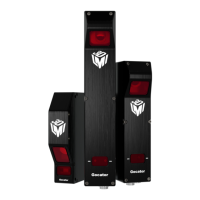
Inverting Outputs
To invert an output, connect a resistor between ground and Out_1- or Out_2- and connect Out_1+ or
Out_2+ to the supply voltage. Take the output at Out_1- or Out_2-. For resistor selection, see above.
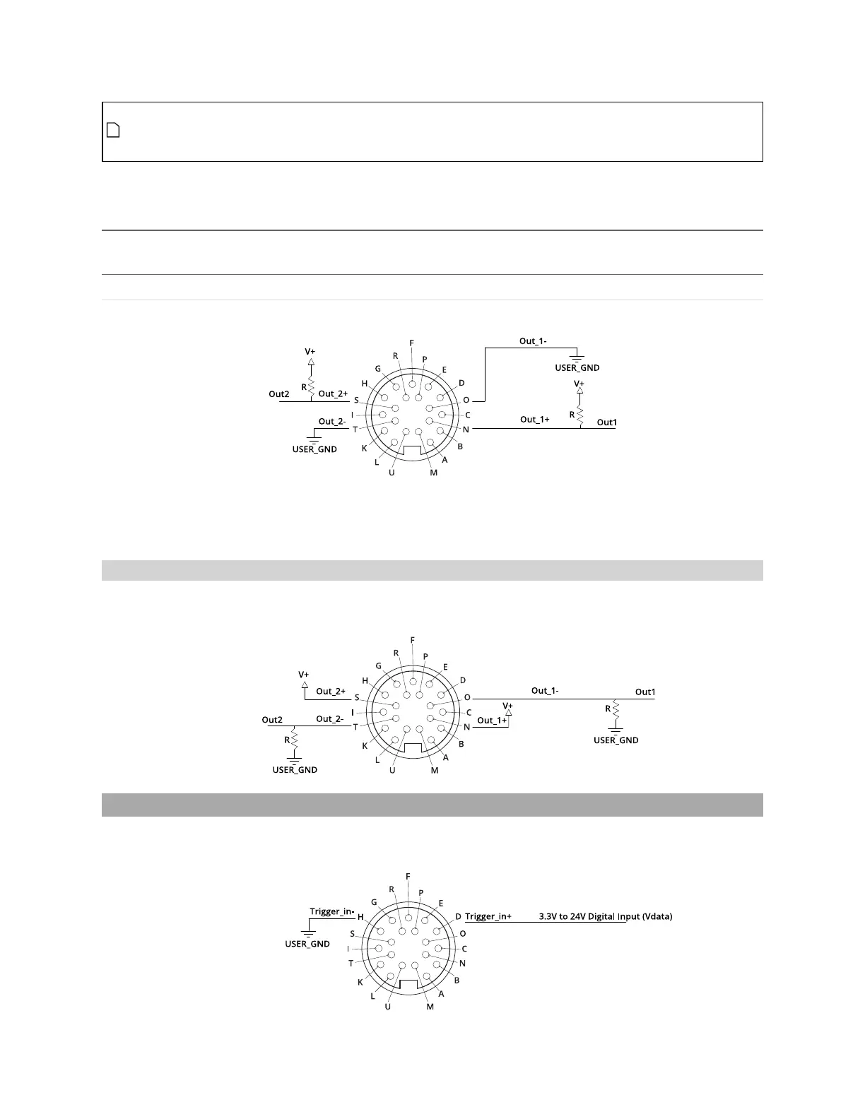
Digital Input
Every Gocator sensor has a single optically isolated input. To use this input without an external resistor,
supply 3.3 - 24 V to the positive pin and GND to the negative.
 Loading...