Gocator Line Profile Sensors: User Manual
Getting Started • 33
Installation
The following sections provide grounding, mounting, and orientation information.
Mounting
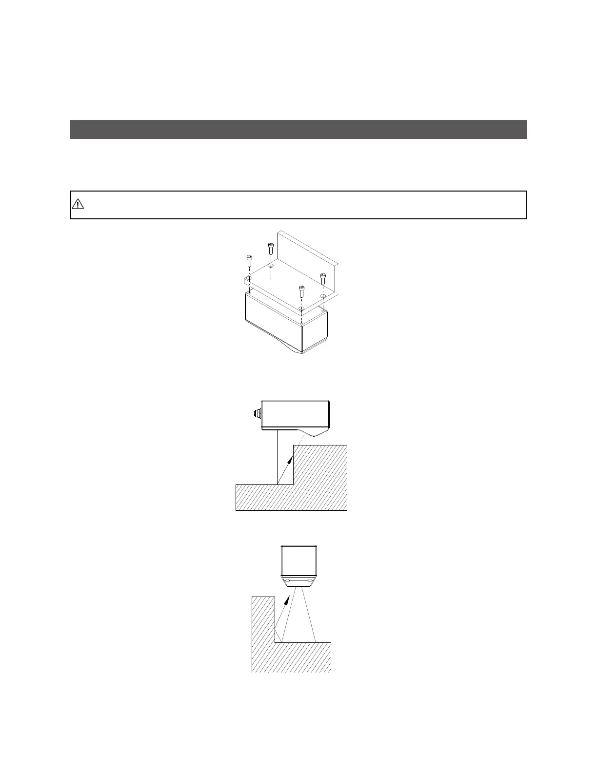
Sensors should be mounted using a model-dependent number of screws. Some models also provide the
option to mount using bolts in through-body holes. Refer to the dimension drawings of the sensors in
Specifications on page 720 for the appropriate screw diameter, pitch, and length, and bolt hole diameter.
Proper care should be taken in order to ensure that the internal threads are not damaged from
cross-threading or improper insertion of screws.
With the exception of Gocator 2880, sensors should not be installed near objects that might occlude a
camera's view of the laser. (Gocator 2880 is specifically designed to compensate for occlusions.)
Sensors should not be installed near surfaces that might create unanticipated laser reflections.
 Loading...

