Gocator Line Profile Sensors: User Manual
How Gocator Works • 58
Profile Output
Gocator represents a profile as a series of ranges, with each range representing the distance from the
origin. Each range contains a height (on the Z axis) and a position (on the X axis) in the sensor's field of
view.
Coordinate Systems
Range data is reported in one of three coordinate systems, which generally depends on the alignment
state of the sensor.
l Sensor coordinates: Used on unaligned sensors.
l System coordinates: Used on aligned sensors. Applies to either standalone or multi-sensor sys-
tems.
l Part and section coordinates:Data can optionally be reported using a coordinate system relative
to the part itself.
These coordinate systems are described below.
For most Gocator 2100, 2300, 2400, and 2800 sensors, X and Y increase as illustrated below,
relative to the connectors. For Gocator 2320, 2410, and 2420, one or both of these axes
increase relative to the laser and camera; for more information, see the coordinate system
orientations illustrated in the specification drawings of these sensors in Sensors on page 720.
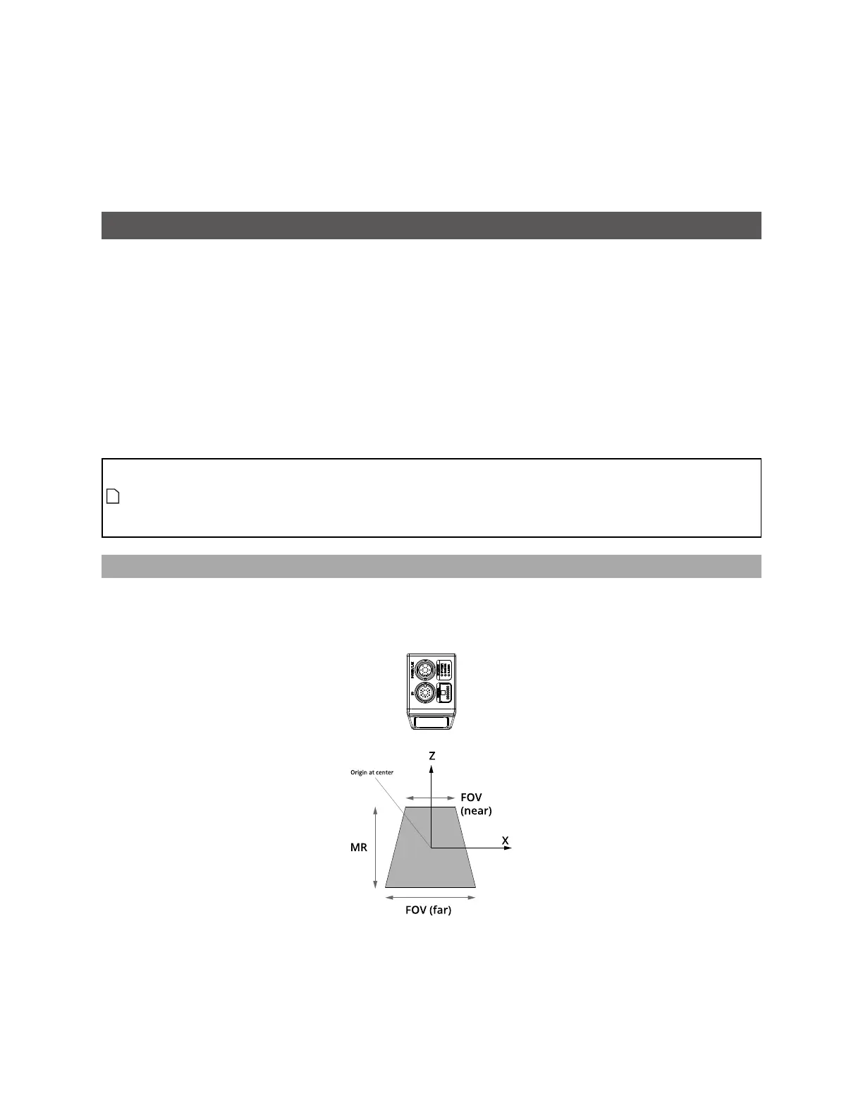
Sensor Coordinates
Unaligned sensors use sensor coordinates: The measurement range (MR) is along the Z axis. The sensor’s
field of view (FOV)is along the X axis. Most importantly, the origin is at the center of the measurement
range and field of view.
Gocator 2130/2330 sensor
 Loading...