Gocator Line Profile Sensors: User Manual
Specifications • 775
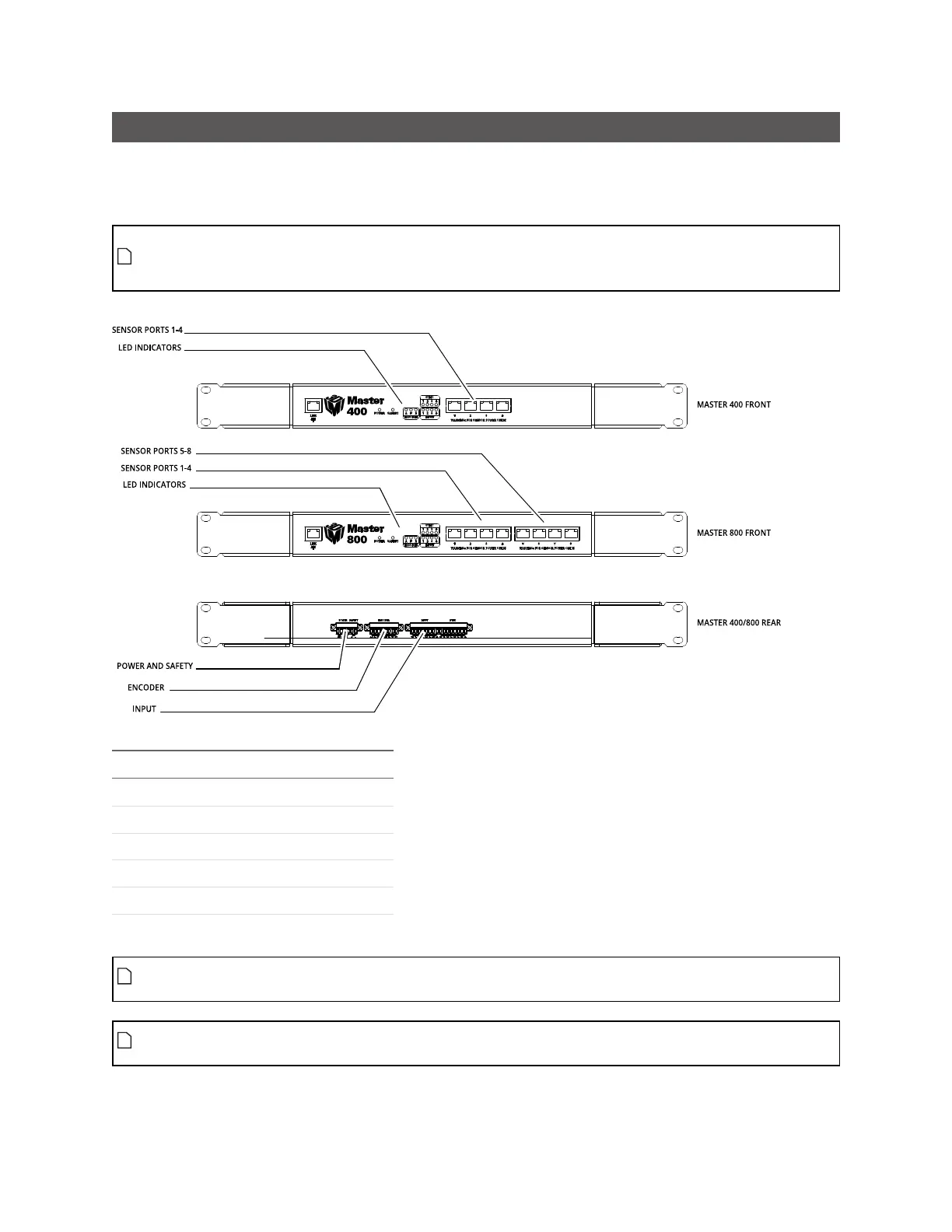
Master 400/800
Master network controllers provide sensor power and safety interlock, and broadcast system-wide
synchronization information (i.e., time, encoder count, encoder index, and digital I/O states) to all
devices on a sensor network.
ThePhoenix connectors on Master 400/800/1200/2400 are not compatible with the connectors
on Master 810/2410. For this reason, if you are switching models in your network, you must
rewire the connections to the Master.
Function Pin
+48VDC 1
+48VDC 2
GND (24-48VDC) 3
GND (24-48VDC) 4
Safety Control+ 5
Safety Control– 6
Power and Safety (6 pin connector)
The power supply must be isolated from AC ground. This means that AC ground and DC ground
are not connected.
The Safety Control requires a voltage differential of 24 VDC to 48 VDC across the pin to enable the
laser.
 Loading...

