Gocator Line Profile Sensors: User Manual
Gocator Web Interface • 193
Maximum spacing interval:lowest profile resolution,
lower sensor CPUusage and data output
Using a higher spacing interval can produce different measurement results compared to using
a smaller spacing interval. You should therefore compare results using different spacing
intervals before using sections in production.
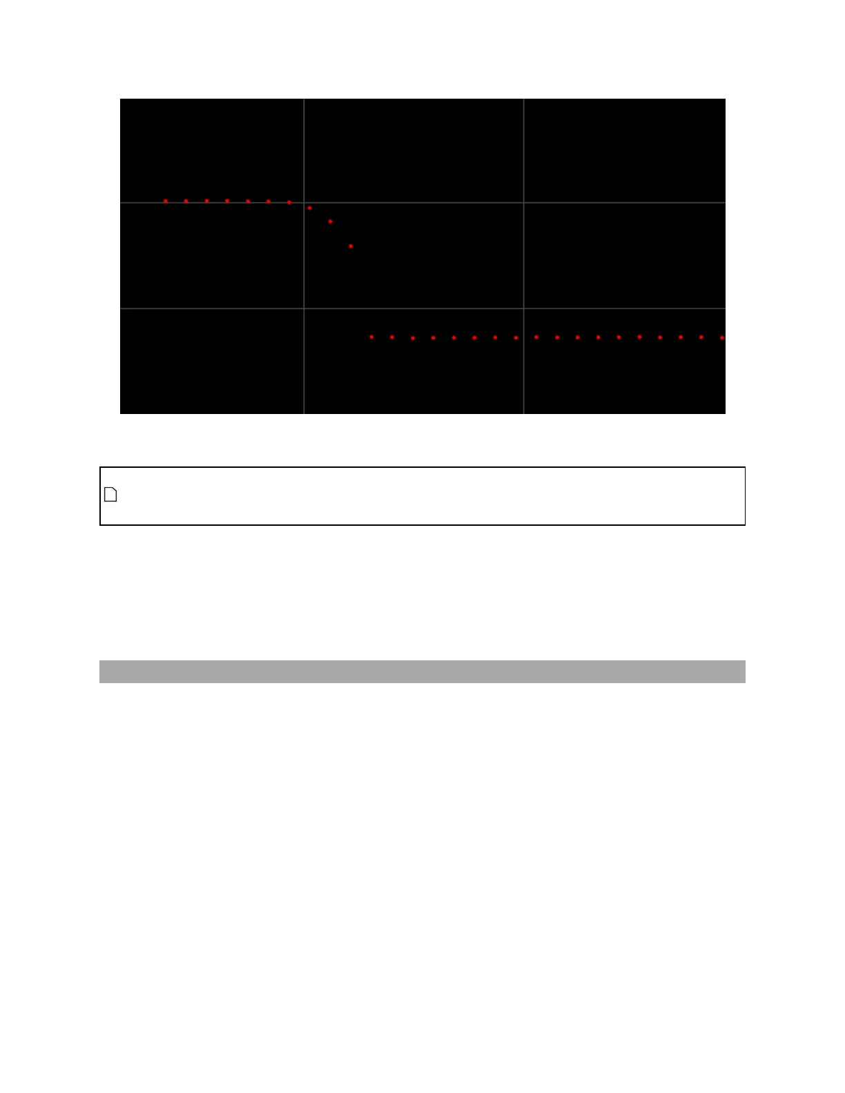
The sections you add to a surface are directional, and their start and end points are defined using X and Y
coordinates. The start point always corresponds to the leftmost point on the extracted profile, whereas
the end point always corresponds to the rightmost point on the extracted profile, no matter the
orientation of the section on the surface.
For more information on profile tools, see Profile Measurement on page 220.
Creating a Section
Before you create a section, you should first scan a target in Surface mode to create a surface on which
you can create the section. You can use either live data or recorded data.
 Loading...