Gocator Line Profile Sensors: User Manual
Gocator Web Interface • 214
If Z Angle anchoring is used with both X and Y anchoring, the X and Y anchors should come from
the same tool.
If Z Angle anchoring is used without X or Y anchoring, the tool's measurement region rotates
around its center. If only one of X or Y is used ,the region is rotated around its center and then
shifted by the X or Y offset.
Several anchors can be created to run in parallel. For example, you could anchor the measurements of
one tool relative to the left edge of a target, and anchor the measurements of another tool relative to
the right edge of a target.
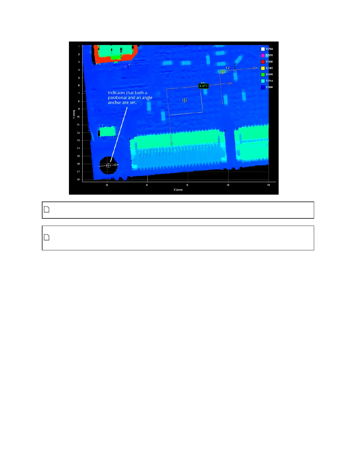
You can combine positional anchors (X, Y, or Z) with angle anchors (Z Angle)for optimum measurement
placement.
To anchor a profile or surface tool to a measurement:
1. Place a representative target object in the field of view.
In Profile mode
a. Use the Start or Snapshot button to view live profile data to help position the target.
In Surface mode
a. Select a Surface Generation type (Surface Generation on page 149) and adjust Part Detection
settings (see Part Detection on page 153) if applicable.
b. Start the sensor, scan the target, and then stop the sensor.
2. On the Measure page, add a suitable tool to act as an anchor.
A suitable tool is one that returns an X, Y, or Z position or ZAngle as a measurement value.
 Loading...