Gocator Line Profile Sensors: User Manual
How Gocator Works • 69
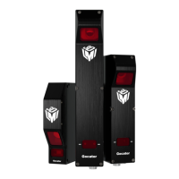
Height measurements rendered a tool's input: a small PCB component (F2) relative to nearby surface (F1),
anchored to positional (X and Y) measurements of the hole (lower right)
and to the Z angle of a larger component to the left (white arrow)
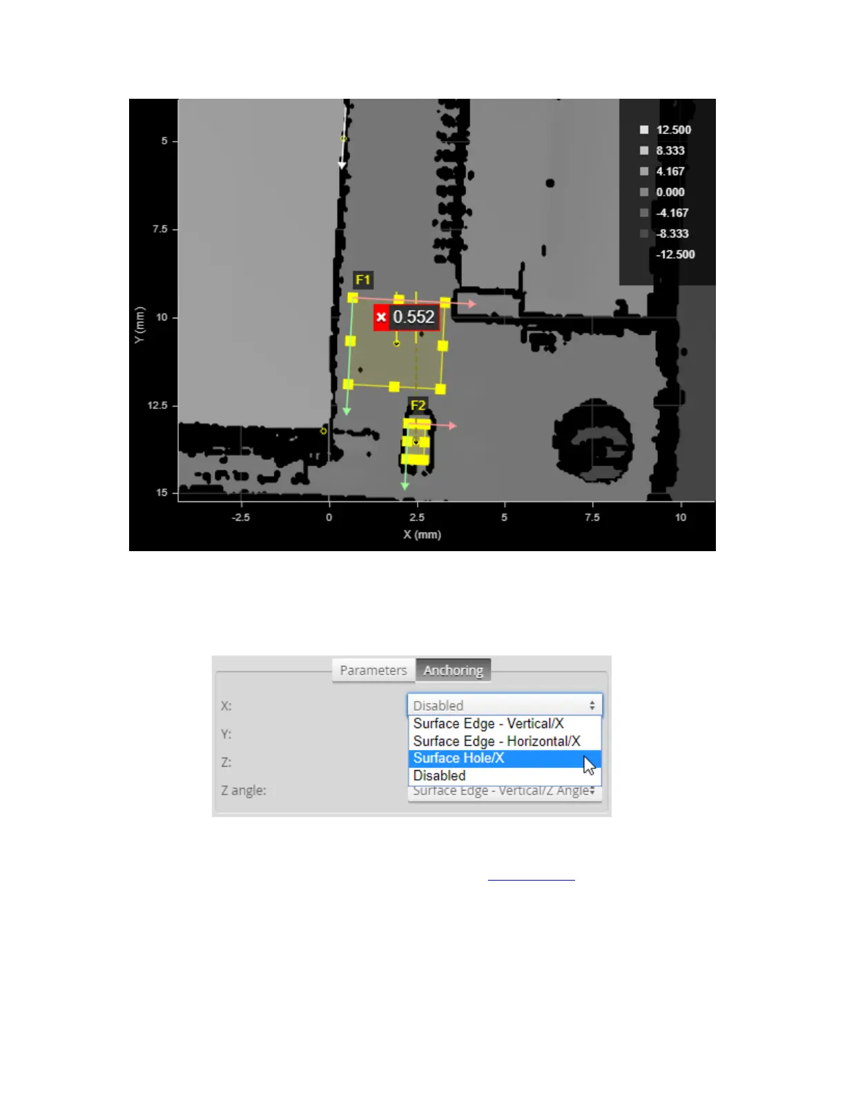
You enable anchoring on the Anchoring tab on the Tools panel:
Note that anchoring is visualized on the anchored tool’s input.
When combined with the matching and rotation capabilities of part matching, anchoring accounts for
most sources of variation in part position and orientation and, consequently, avoids many measurement
errors. For more information on anchoring, see Measurement Anchoring on page 211.
 Loading...