Gocator Line Profile Sensors: User Manual
Specifications • 780
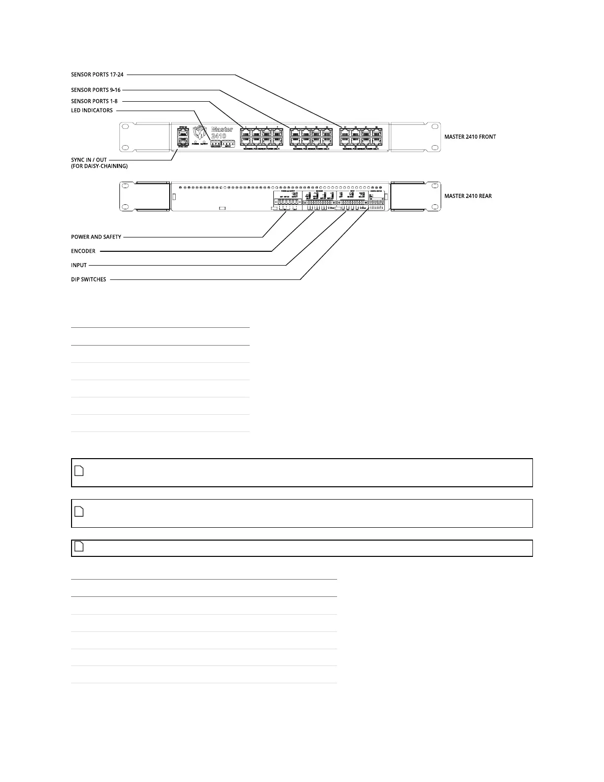
For information on configuring the DIPswitches, see Configuring Master 810 on page 40.
Function Pin
Power In+ 1
Power In+ 2
Power In- 3
Power In- 4
Safety Control+ 5
Safety Control– 6
Power and Safety (6 pin connector)
The power supply must be isolated from AC ground. This means that AC ground and DC ground
are not connected.
The Safety Control requires a voltage differential of 24 VDC to 48 VDC across the pin to enable the
laser.
On earlier revisions of Master 810 and Master 2410, the inputs are labeled 0-3.
Function Pin
Input 1 Pin 1 1
Input 1 Pin 2 2
Reserved 3
Reserved 4
Reserved 5
Input (10 pin connector)
 Loading...