OPERATION
The optional M105 transport drawbar (MD #B5411) mounts
to the walking beam and provides approximately 12 in.
(300 mm) of fore-aft movement to ease the attachment of a
towed implement. Refer to 7.1.18 Transport Drawbar, page
340 for more information.
Attach the tow-bar to the windrower as follows:
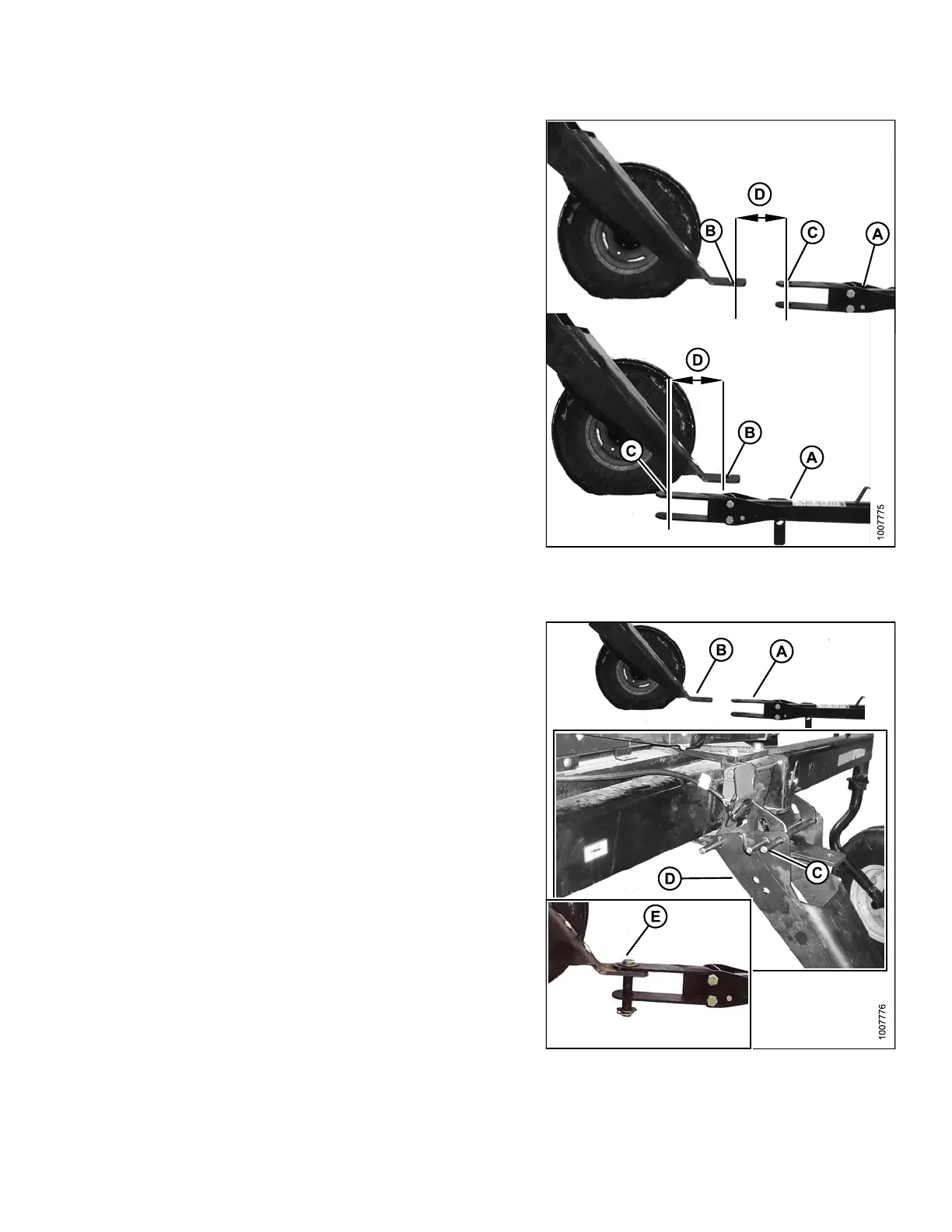
24. Back the windrower up to the tow-bar (A) so that the
drawbar hole (B) is within 6 in. (150 mm) (D) of the
tow-bar clevis pin (C).
25. Stop engine, and remove key.
Figure 4.
43: Towing Components
A - Tow-Bar B - Drawbar Hole
C - Tow-Bar Clevis Pin D - Within 6 inches (150 mm)
26. If the to w-ba r (A) is TOO FAR from the drawbar (B):
a. Remove pin (C), lift the drawbar support (D) until
the tow-bar clevis aligns, and then install the
drawbar pin (E).
b. Start engine, and gently reverse th e windrower
until the drawbar support pivots down to
transport position.
c. Stop engine, and remove key.
d. Reinstall pin (C) to secure drawbar support, and
connect the safety chain. Proceed to step 28.,
Converting from Field to Transport Mode, page
110.
IMPORTAN T:
Ensure lynch p ins a re secure in all three pin s, and that
the drawbar pin is also secured by a locking pin.
Figure 4.44: Towing Components
169890 109 Revision A