MAINTENANCE AND SERVICING
Removing Drive W heel
CAUTION
Use a suitable lifting device capable of supporting
aminimumof2000lbs(907kg)toliftthewheel
assembly away from the windrower.
1. Raise the windrower drive wheel (A) off the ground.
Refer to Raising Drive W heel, page 303.
2. Remove the wheel nuts (B).
3. Remove the driv e wheel (A).
Figure 5.1
99: Dri ve Wheel Assem bly
Installin
g Drive Wheel
NOTE:
Windrower must be supported off the ground with stands.
Refer to Raisin g D rive Wheel, pa ge 303.
1. Position drive wheel (A) against wheel drive hub (B),
so that air valve (C) is on the outside and tire tread (D)
points forwa rd.
For Turf tires (diamond tread), be sure arrow on
sidewall points in forward rotation.
2. Lift wheel on hub with lifting device.
3. Lower lifting device.
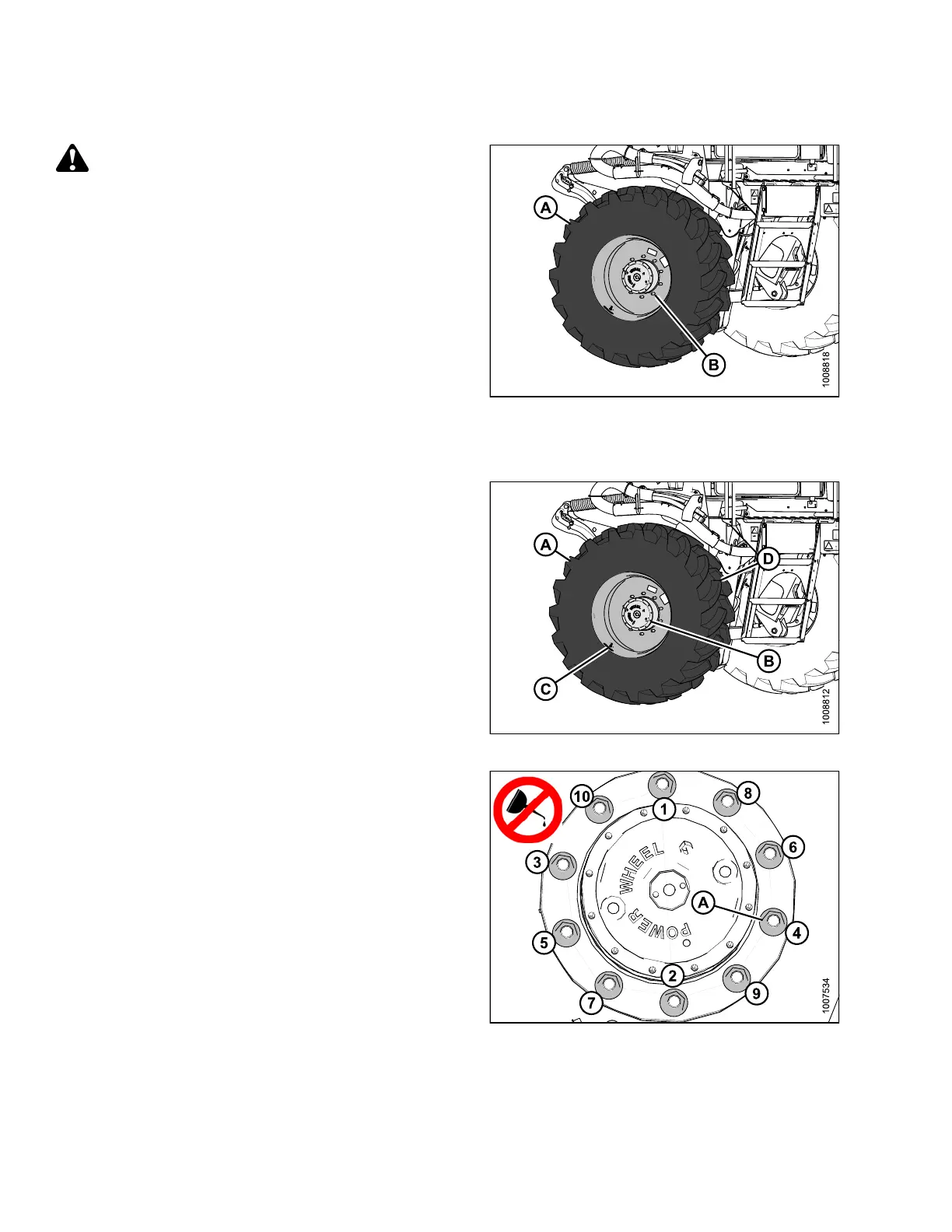
Figure 5.200: Drive Wheel Assembly
4. Line up the holes in the rim with the s tuds on the wheel
drive hub and install wheel nuts (A).
NOTE:
To a v o
id damage to wheel rims and studs, tighten nuts by
hand,
do NOT use an impact gun, do NOT use lubricant
or Ne
ver-Seez
®
compound, and do NOT overtighten
whee
lnuts.
5. Torque drive wheel nuts. Refer to Tighten ing Drive
Wheel Nuts, page 299.
6. Lower the windrower, and remove jack. Refer to
Lowering Drive Wheel, page 305.
7. After one hour of operation, retorque the wheel nuts.
Then check every hour until two consecutive checks
produce no movement of the nuts.
Figure 5.201: Drive Wheel Nuts
169890 304 Revision A