Section 22: HEATING AND AIR CONDITIONING
PA1553
6
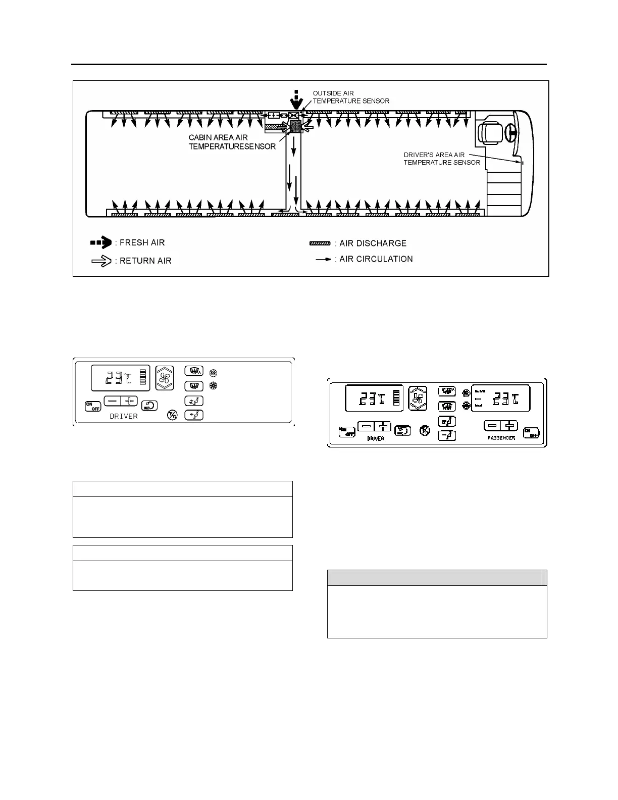
FIGURE 3: CENTRAL HVAC SYSTEM AIR CIRCULATION 22334
4. SMALL HVAC SYSTEM OPERATION
Only the temperature in the driver’s area is
controlled by the HVAC control module mounted
on the R.H. dashboard panel (Fig. 4).
FIGURE 4: SMALL HVAC SYSTEM CONTROL MODULE22184
Using the Up/Down type switch sets the fan
speed and the speed chosen is displayed on the
HVAC control module.
NOTE
The driver’s area air temperature sensor is
located behind the grill of the R.H. side
console.
NOTE
The outside air temperature sensor is located
behind the front bumper on the L.H. side.
5. CENTRAL HVAC SYSTEM OPERATION
To operate the air conditioning system when
coach is stationary, engine should run at fast
idle. During operation of the air conditioning
system, windows should be kept closed and
door not left open longer than necessary. In
order to prevent battery discharge, HVAC
system will not operate if vehicle charging
system is not working properly.
5.1 DRIVER’S UNIT OPERATION
The temperature control in the driver’s area is
provided directly by the L.H. portion of the HVAC
control module mounted on the R.H. dashboard
panel (Fig. 5).
FIGURE 5: CENTRAL HVAC SYSTEM CONTROL
MODULE
The driver’s HVAC unit piping is paralleled with
the cabin HVAC unit piping. Both units use the
same refrigerant and coolant, and are linked to
the same condenser and compressor, even if
they are individually controlled. It requires the
cabin HVAC unit to engage the A/C compressor
magnetic clutch. Consequently, the driver’s unit
cannot be operated in the A/C mode alone.
NOTE
The driver's HVAC unit turns on automatically
at starting of the engine and uses the settings
that were kept in memory before turning off of
the system.
The A/C compressor starts automatically when
the two following conditions are satisfied:
1. The outside temperature is above 32°F
(0°C).
2. The cabin area air temperature has
reached 7°F (4°C) under the set point.
 Loading...


