Section 22: HEATING AND AIR CONDITIONING
PA1553
41
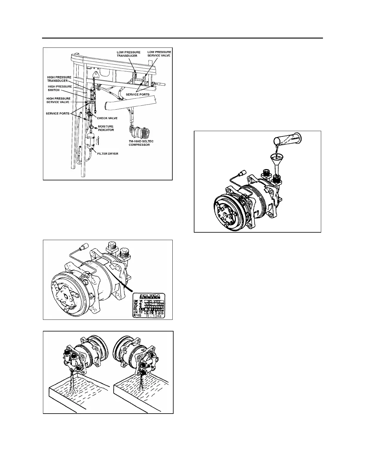
FIGURE 43: SMALL A/C SYSTEM REAR COMPONENTS
10.6 COMPRESSOR OIL CHANGE
Each compressor is delivered filled with the
specified quantity of compressor oil, depending
on the type of air conditioning system. A label
describing the amount/type of compressor oil is
attached to the compressor.
FIGURE 44: COMPRESSOR OIL LABEL
FIGURE 45: DRAINING THE OIL
* Check oil for contamination. Refer to
PARAGRAPH 10.8: “COMPRESSOR OIL
CONTAMINATION”.
* Tighten the oil drain plug with a new o-ring
lightly coated with clean compressor oil to
specified torque.
Torque: 13-15 Nm (9.4-10.8 Lbf-ft)
* Add new compressor oil through the
suction-side connector with the amount
specified on the label (180 ml).
FIGURE 46: ADDING NEW COMPRESSOR OIL
10.6.1 Evacuating System Before Adding
Refrigerant (Small System)
When a system has been opened for repairs,
change the filter dryer and evacuate the system.
XL2 MTH equipped with a small system must
use high-pressure service port located on the
other side of check valve and low-pressure port
located alongside rear truss. (Figs. 42 and 43). It
would be good practice to open solenoid valve.
1. Connect two hoses equipped with a micron
gauge between the high-pressure service
port, the low-pressure service port and the
vacuum pump.
2. With the unit service valves open and the
vacuum pump valves open, start the pump
and draw the manifold and hoses into a
very deep vacuum (700 microns).
3. Close manifold valve
4. Shut down the vacuum pump.
5. Check to insure that vacuum holds. (If the
pressure continues to rise, it indicates a
leak or moisture in the system).
 Loading...


