Section 6: ELECTRICAL
PA1553
51
12. EXTERIOR LIGHTING
The circuit for exterior lights, as well as their
control switches, relays and circuit breakers are
shown on the applicable wiring diagrams. Wiring
diagrams are located in the technical publication
box.
12.1 HEADLIGHTS
Each headlight assembly consists of two
headlamp module 90 mm (3½ inch) equipped
with a 12-volt halogen bulb and one 100 mm
(4 inch) 12-volt LED turn/signal lamp. Outer
lamps have a double function (both low and high
beam). Inner lamps are used for high beam or
daytime running light. The inner or outer lamp
uses the same single filament halogen bulb part
number.
NOTE
If vehicle is equipped with optional Xenon
headlamps, refer to paragraph 12.1.6.
FIGURE 40: HEADLIGHT ASSEMBLY 06546
12.1.1 Headlight Beam Toggle Switch
The multifunction lever located on the steering
column is used to select proper lighting. High
beams or low beams can be selected by pulling
the lever rearward. A high beam indicator on the
central dashboard panel is illuminated when the
high beam circuit is energized.
NOTE
Pulling the lever rearward while the lights are
off will flash the headlights.
12.1.2 Maintenance
Clean headlights with soap and water and a
good glass cleaner whenever dirty. For
maximum illumination, headlight connections
must be coated with a dielectric grease to
prevent oxidation and proper voltage must be
maintained. Low battery voltage, loose or dirty
contacts in wiring system and poor ground
contribute to a decrease in voltage. Check
wiring and connections regularly and keep
battery properly charged. When a headlight
burns out, a new bulb must be installed.
Headlights must be properly aimed to provide
maximum allowable road illumination. When
using mechanical aiming devices, follow
manufacturer’s instructions.
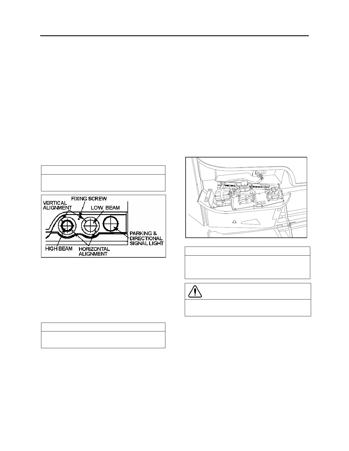
Headlight aim should be checked after installing
a new bulb. Aiming can be performed without
opening headlight assembly. Horizontal and
vertical aiming of each module is provided by
two adjusting screws that pivot the module in the
housing for proper alignment (fig. 40). There is
no adjustment for focus since the module is set
for proper focus during manufacturing assembly.
FIGURE 41: OPENING HEADLIGHT ASSEMBLY 06547
NOTE
Make sure headlight assembly is properly
positioned into its housing before securing
using fixing screw.
CAUTION
Use a soft cloth to clean the parking and front
turn signal lamp.
12.1.3 Headlight Adjustment
The following is a general procedure for
headlight adjustment using mechanical
equipment, such as a “Hoopy 100” Aligner. If
your mechanical equipment is different, refer to
the manufacturer’s instruction manual.
 Loading...


