Section 26: XLII SLIDE-OUT
PA1553
15
To remove, loosen the set screw and release the
locking collar using channellock pliers or a small
pipe wrench.
11 LINEAR BEARING
11.1 MAINTENANCE
Make every effort not to allow dust and foreign
objects to enter inside the linear bearing.
The linear bearings are pre-lubricated and no
subsequent lubrication is required due to the
very low demanding use of the slide-out system.
11.2 REPLACEMENT &
ADJUSTMENT
1. Remove the slide-out from the vehicle
(removal must be performed according to
the Slide-Out Removal Procedure. Ask to
your Prevost service representative).
2. Disconnect the jaw coupling on the side of
the linear bearing being replaced (refer to
section 8).
3. Dismount the blue flange bearing.
4. From the mechanism access panel, remove
the retaining screws A, B, C & D (see figure
22).
5. Now, you have access to the linear bearing
mounting bolts if you turn its support up side
down. Dismount the linear bearing and
install the new one.
6. Tighten the mounting bolts in a criss-cross
pattern to a torque of 60 ft-lb.
7. Reinstall the support plate, retaining screws,
blue flange bearing and reengage the jaw
coupling. Refer to the specific procedures.
11.3 LEVEL & TILT ADJUSTMENT
Leveling of the slide-out is done by changing the
linear bearing support plate height using the
leveling screws 1, 2, 3, 4 (figure 22). When
proper level is attained, the retaining screws A,
B, C & D maintain the support plate seated on
the leveling screws. Also, the retaining screws
prevent the slide-out from tipping inside the
vehicle when it is retracted.
The slide-out is slightly tilted. When retracting,
the upper "in limit" stoppers touch first
the
vehicle structure, followed by the lower "in limit"
stoppers. Tilt adjustment is done by changing
the linear bearing support plate inclination using
the leveling screws 1 & 2 as pivot and 3 to adjust
the angle (figure 22).
11.3.1 Procedure
NOTE
For the front slide-out, the front linear
bearing leveling screws are accessible from
the access panel located over the front wheel
while the rear linear bearing leveling screws
are accessible from the access panel in the
evaporator compartment. For the rear slide-
out, access the linear bearing from under the
bed structure or the radiator compartment.
WARNING
The slide-out must be retracted when the level
and tilt adjustment is performed.
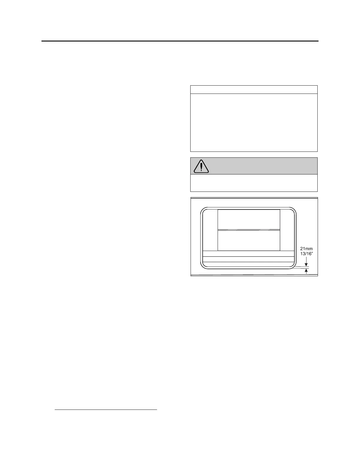
FIGURE 21: SLIDE-OUT LEVEL ADJUSTEMENT
Before proceeding with the level and tilt
adjustment, check the following conditions:
• The slide-out is retracted;
• The 2 lower “in limit” stoppers are perfectly
adjusted, that means that the lower edge
of the slide-out outer panel is flush with
the vehicle body when retracted;
• The 2 upper “in limit” stoppers are
removed from the slide-out (see
section1.2).
1. Loosen the blue flange bearings mounting
screws (FIGURE 13).
2. For front slide-out only, loosen the two
plastic plates mounting screws along the
shafts (FIGURE 13).
3. With the lower edge of the slide-out outer
panel flush with the vehicle body, adjust the
 Loading...


