Section 22: HEATING AND AIR CONDITIONING
PA1553
44
10.13 CONDENSER COIL
The condenser coil, for vehicles equipped with a
small A/C system is mounted on the outer face of
engine radiator. Since condenser’s purpose is to
dissipate heat from the hot refrigerant, it is
important to keep the cooling coils and fins
clean. A clogged coil will cause high discharge
pressure and insufficient cooling.
10.14 FILTER DRYER
The filter dryer is located close to engine
compartment L.H. side door on vehicles equipped
with the small A/C system (Refer to fig. 43). Its
function is similar to that of filter used on central
system. Replace only when system is opened or
a problem occurs.
10.15 MOISTURE INDICATOR
The moisture sensitive element consists of a
color changing ring which is reversible from pink
to blue and vice versa as the moisture content in
the refrigerant changes. Pink indicates a wet
refrigerant, light violet (caution) and blue
indicates a dry refrigerant.
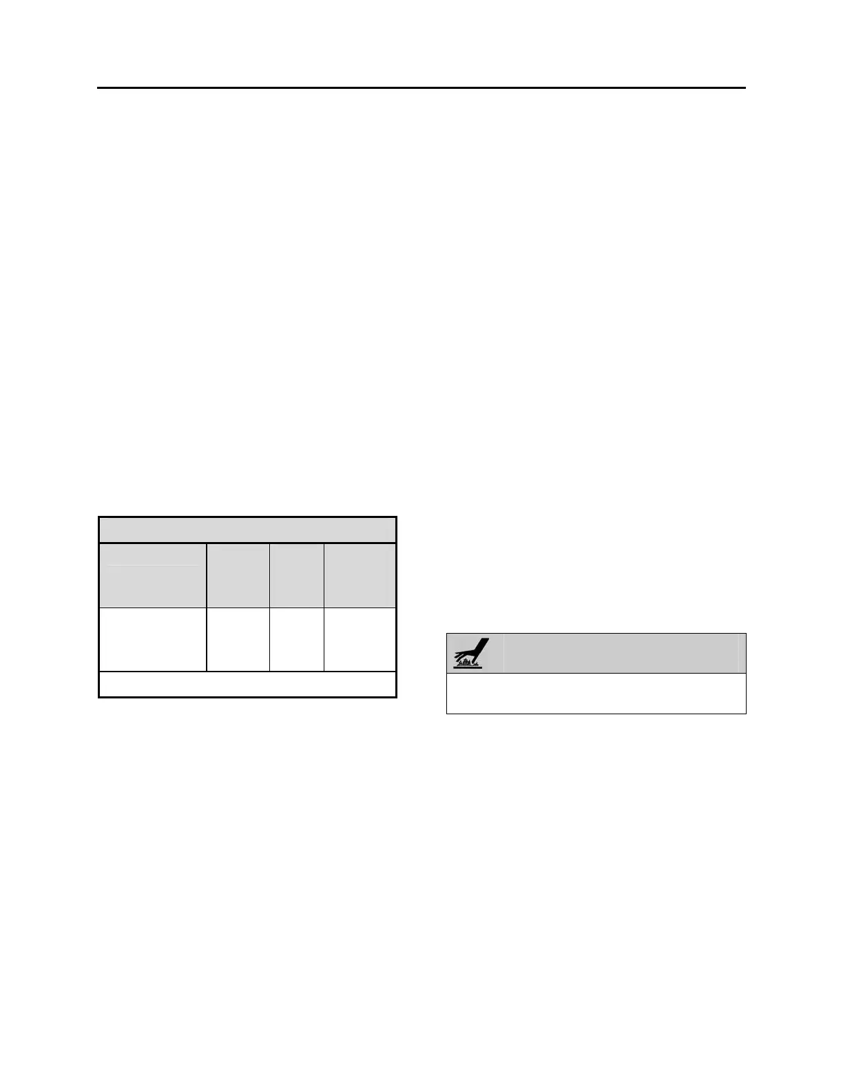
COLOR INDICATOR
TEMPERATURE
BLUE
(ppm)
LIGHT
VIOLET
(ppm)
PINK
(ppm)
75°F (24°C)
100°F (38°C)
125°F (52°C)
Below 5
Below 10
Below 15
5-15
10-30
15-45
Above 15
Above 30
Above 45
p.p.m.= parts per million (moisture content)
Since temperature changes affect the solubility,
color change will also vary with the refrigerant
temperature. The above table shows the color
change for R-134a at various moisture levels
and liquid line refrigerant temperatures.
A moisture level of less than 15 p.p.m. for R-
134a indicated in the blue color range of the
above table is generally considered dry and
safe. A color indication of light blue to light violet
indicates the caution range of moisture level.
For positive protection, the drying of the system
should be continued until the color of the
element turns to deep blue.
The liquid refrigerant is readily visible through
the center opening of the moisture element
where the presence of bubbles indicates a
shortage of refrigerant or restriction in line.
11. HEATING SYSTEM
As seen earlier in this section, the vehicle
interior is pressurized by its Heating, Ventilation
and Air Conditioning (HVAC) system. Two
heating systems are available: Central Heating
System and Small Heating System. The vehicle
interior should always be slightly pressurized to
prevent cold and moisture from entering. If the
vehicle is equipped with a Central Heating
System; air flow and controls divide the vehicle
into two areas: driver’s area and cabin area.
The schematic of Figure 50 shows the central
heating system with its components.
11.1 CENTRAL HEATING SYSTEM
11.1.1 Draining Heating System
To drain the entire system, refer to Section 05,
“Cooling”. If only the driver’s HVAC unit or cabin
HVAC unit heater core must be drained, refer to
the following instructions.
o Draining Driver’s HVAC Unit Heater Core
a) Stop engine and allow engine coolant to
cool.
b) Locate the normally open hot water
pneumatic valve on the ceiling of the
spare wheel compartment (Fig. 51), move
the pilot-solenoid valve red tab to close
the valve.
WARNING
Before proceeding with the following steps,
check that coolant has cooled down.
c) Loosen hose clamp, install an appropriate
container to recover coolant, and
disconnect silicone hose from hot water
pneumatic valve.
d) From inside of vehicle, remove the two
finishing panels in front of unit. Remove
the three screws fixing the unit front panel.
Open the manual vent located inside the
HVAC unit, on the driver’s side (Fig. 52) to
ensure an efficient draining.
 Loading...


