Section 12: BRAKE AND AIR SYSTEM
PA1553
8
8.6 MAINTENANCE
Inspect all lines for cuts, swelling, kinks or other
damage or deterioration. Check for lines being
pinched by other components. Retaining clips
and ties must be in place.
Any support or bracket should be in good
condition and mounted firmly in position. Hose
spring guards should be in usable condition and
not distorted. Particular attention should be
given to long lines. Any supporting component
(clips, ties, grommets, etc.) must be secured to
prevent against unnecessary vibration and
eventual loosening of connection. Any detected
leak should be repaired. Be sure nylon lines are
not near areas of intense heat. Check for any
missing grommets or loose material where
chafing or cutting may occur. Replace with new
material as required. In general, lines should be
securely located in position and free from any
binding condition which would hinder air flow.
9. PRESSURE REGULATING VALVES
There is one pressure regulator for the belt
tensioners, and an optional one installed on
vehicles equipped with the Allison transmission
output retarder.
The belt tensioner pressure regulating valve is
located in the engine compartment above the
doors and is used to limit the air pressure in belt
tensioners to 50 ± 2 psi (345 ± 15 kPa) for WE
and W0 MTH and to 45 ± 2 psi (310 ± 15 kPa)
for W5 MTH (Fig. 7).
The optional regulator is located above the rear
junction box in the engine compartment
(accessible through the engine R.H. side door).
It is used for transmission retarder and should
be adjusted to 80 ± 3 psi (550 ± 20 kPa).
Air Pressure
(psi)
Air Pressure
(kPa)
Belt
Tensioner
Series 60
50 (WE & W0)
45 (W5)
Series 60
345
310
Retarder 80 ± 3 550 ± 20
9.1 MAINTENANCE
Every 100,000 miles (160 000 km) or once every
two years, whichever comes first, disassemble
the regulating valve and wash all metal parts in
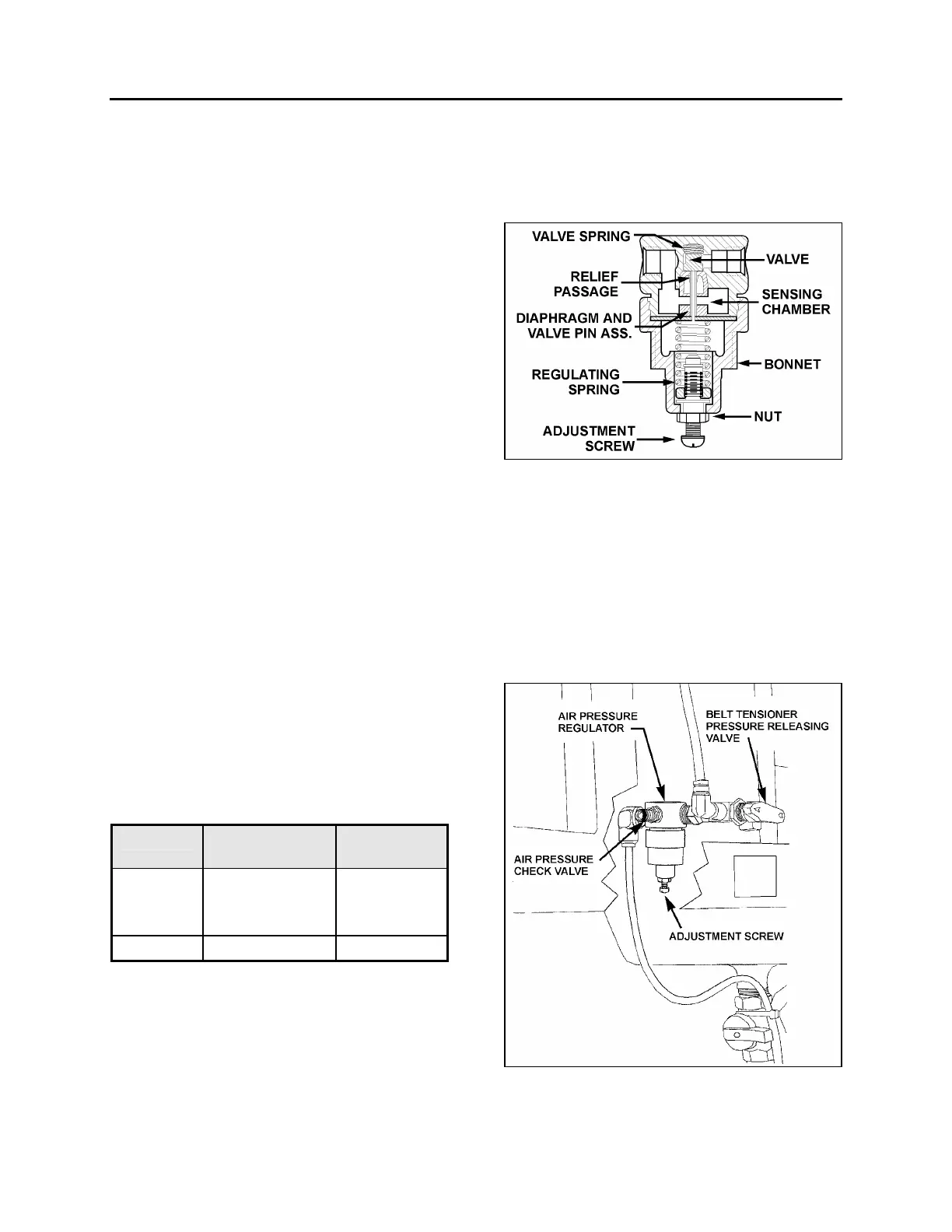
a cleaning solvent (Fig. 6). Examine the
diaphragm; if cracked, worn or damaged,
replace with a new one. If the valve is
excessively grooved or pitted, it should be
replaced. Replace any other part that appears
worn or damaged. After reassembly, adjust to
the specified pressure setting and check for air
leakage.
FIGURE 6: AIR PRESSURE REGULATING VALVE 12141B
9.2 PRESSURE SETTING PROCEDURE
Remove the dust cap from the pressure check
valve (Fig. 7). Attach a pressure gauge at this
port and check the pressure reading. If the
pressure reading is incorrect, adjust as follows:
1. Loosen the locking nut, turn the adjustment
screw counterclockwise to decrease pres-
sure by approximately 10 psi (70 kPa) below
the required pressure.
FIGURE 7: AIR PRESSURE REGULATOR 12200
 Loading...


