Section 26: XLII SLIDE-OUT
PA1553
13
6 ELECTRIC MOTOR
The power is supplied by a 24V 1/3 HP electric
motor coupled with a speed reduction gearbox.
Opposite to the gearbox, the motor is equipped
with a 3/8 hexagonal socket shaft extension
permitting to move the slide-out without using
the handheld control. This is very useful when
moving the slide-out very slowly is required like
during the inner stoppers adjustment, the tilt
adjustment or the 2" inside retraction. See
section 18 for the manual override procedures.
CAUTION
When moving the slide-out with a cordless
power drill as described in the manual
override procedure, be careful as the slide-out
approaches its opened or closed position, in
order not to overload the mechanism.
6.1 MAINTENANCE
Inspect the electrical connections and their
watertightness. Check that the mounting bolts
are tight (FIGURE 18).
6.2 REPLACEMENT
1. The slide-out must be retracted.
2. Unplug the electric cable connector.
FIGURE 17: ELECTRIC MOTOR AND SPEED REDUCTION
GEARBOX
3. Remove the motor from the gearbox.
4. Fasten the new motor to the gearbox using
screws.
5. Re-connect the electric cable connector.
7 SPEED REDUCTION
GEARBOX
The speed reduction gearbox used is a helical
worm gear type. This gearbox has a 2-stage
740:1 ratio and the output shafts are self-locking.
Keys on output shafts are glued into keyseats.
7.1 MAINTENANCE
Inspect the gearbox to check if there is any
leakage or backlash in the box. Replace the
gearbox if excessive wear is present. Check that
all bolts are tight.
The gearbox is lubricated for life and the oil
should not have to be changed.
7.2 GEARBOX REPLACEMENT
1. The slide-out must be retracted.
2. Disengage the shafts jaw couplings (refer to
section 8: JAW COUPLING).
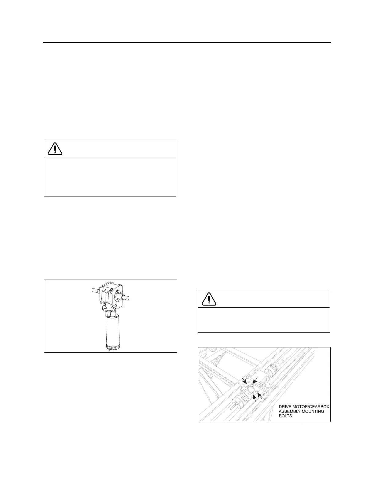
3. Remove the 4 cap screws securing the drive
motor/gearbox assembly and dismount the
assembly (see FIGURE 18).
4. Remove the gearbox from the motor and
install the new one.
5. Reinstall the drive motor/gearbox assembly
on the vehicle mounting bracket. Tighten
mounting bolts to a torque of 18 lbf-ft in a
criss-cross patern.
CAUTION
To prevent damaging threads, use your
fingers to drive the bolts into the aluminum
gearbox housing mounting holes.
6. Reinstall the jaw couplings.
FIGURE 18: DRIVE MOTOR/GEARBOX ASSEMBLY
MOUNTING BOLTS
 Loading...


